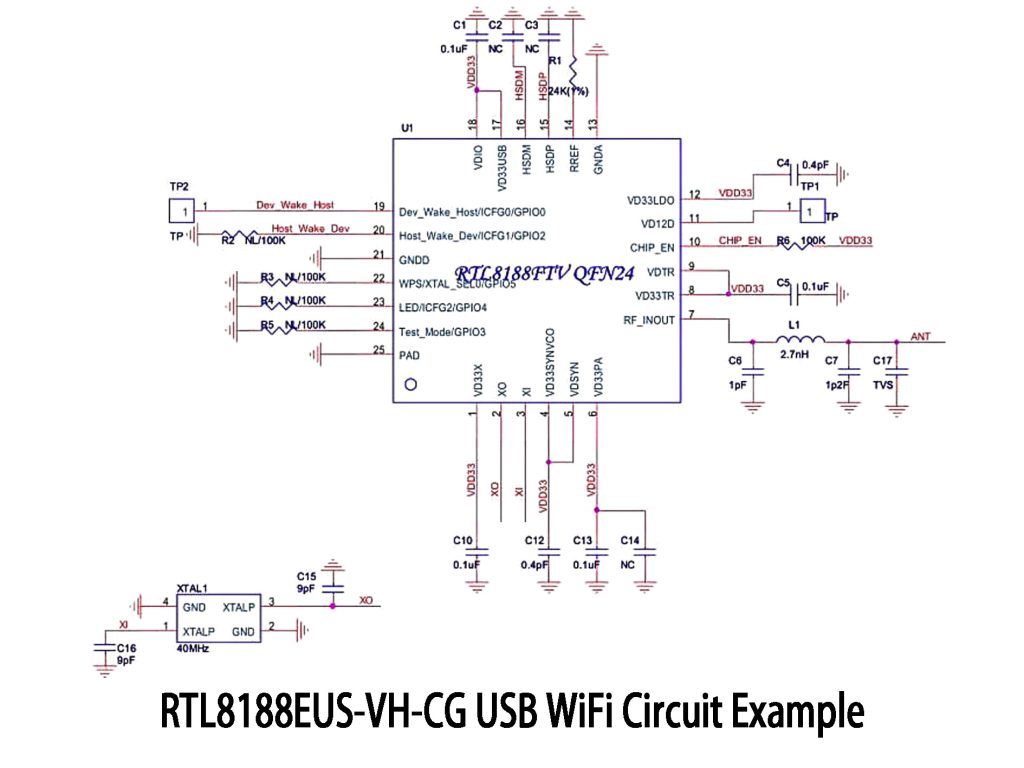
The main chip in the picture is the RTL8188FTV QFN24, basically the same as RTL8188EUS just packaged differently—common in USB WiFi designs. Pins 15 and 16 handle USB data, protected by standard EMI/ESD resistors and capacitors. Pin 7 connects to an antenna matching network and TVS for static protection, typical in RTL8188 designs. It uses a 40MHz crystal oscillator, and power pins include proper decoupling caps and pull-up resistors for stability. Plus, GPIO pins for wake-up functions help manage low-power sleep modes effectively.

RTL8188EUS-VH-CG datasheet & price | pdf
Discover the comprehensive RTL8188EUS-VH-CG Reference Manual, available in pdf format. Find detailed information about specifications and pricing to help you make informed decisions for your projects.
- Brands: Realtek Semicon
- Download: -
- Price: inquiry
- In Stock: 9821
- Type: -
- Protocol: -
- Data Rate: -
- Package: LQFN-46-EP(4.5x6.5)


FREE delivery for orders over HK$250.00

Quick response, quick quotaton

Flash shipment,no worries after sales

Original channel,guarantee of the authentic products
Antena wifi Realtek RTL8188EUS USB de una tablet descompuesta
RTL8188EUS-VH-CG
The RTL8188EUS-VH-CG is a USB WiFi controller from Realtek that’s widely used in compact USB WiFi modules. It supports 802.11b/g/n standards, giving you speeds up to 150Mbps—good enough for regular browsing and streaming videos. It comes with built-in USB 2.0 PHY, running smoothly on the common 2.4GHz band. Plus, it integrates an LNA, power amplifier, and RF switch, saving you from adding extra RF components. You can use either a PCB antenna or an external antenna through an IPEX connector. It’s also fully compatible with Linux, Windows, and Android, perfect for your DIY wireless projects.
RTL8188EUS-VH-CG Pinout
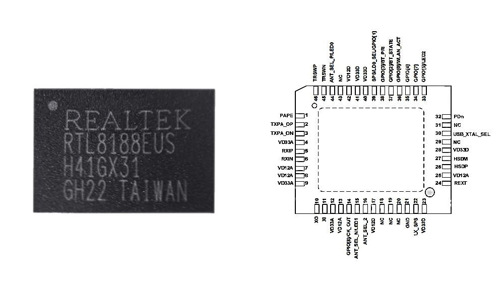
| Pin No. | Name | Type | Description |
|---|---|---|---|
| 1 | PAPE | O | 2.4 GHz TX PA Enable |
| 2 | TXPA_OP | O | RF TX Negative Output |
| 3 | TXPA_ON | O | RF TX Positive Output |
| 4 | VD33A | P | Analog Power 3.3V |
| 5 | RX_IP | I | RF RX Positive Input |
| 6 | RX_IN | I | RF RX Negative Input |
| 7 | VD12A | P | Analog LDO Output 1.2V |
| 8 | VD12A | P | Same as above |
| 9 | VD33A | P | Analog Power 3.3V |
| 10 | XO / LED0 / ANT_SEL_P | O | Crystal Output / LED0 / Antenna Positive Control |
| 11 | XI | I | Crystal Input (25/40 MHz) |
| 12 | VD33A | P | Analog Power 3.3V |
| 13 | VD12A | P | Analog LDO Output 1.2V |
| 14 | GPIO8 / CK_OUT | IO | GPIO or Clock Output |
| 15 | ANT_SEL_N / LED1 | O | Antenna Negative Control / LED1 |
| 16 | ANT_SEL_2 | O | Antenna Extension Control |
| 17 | VD12D | P | Digital LDO Output 1.2V |
| 18–20 | NC | – | No Connection |
| 21 | GND | P | Ground |
| 22 | LX_SPS | P | Switch Regulator Output |
| 23 | VD33D | P | Digital Power 3.3V |
| 24 | REXT | O | Bandgap Reference Pull-down |
| 25 | VD12A | P | Analog LDO Output 1.2V |
| 26 | VD12D | P | Digital LDO Output 1.2V |
| 27 | USB_DM / HSDM | IO | USB D– Line |
| 28 | VD33D | P | Digital Power 3.3V |
| 29 | NC | – | No Connection |
| 30 | USB_XTAL_SEL | I | Crystal Frequency Select (0=25 MHz, 1=40 MHz) |
| 31 | NC | – | No Connection |
| 32 | PDn | I | Power Down Input |
| 33 | GPIO5 / LED2 | IO | GPIO or LED2 |
| 34 | GPIO7 | IO | GPIO (Supports RF Shutdown) |
| 35 | VD33D | P | Digital Power 3.3V |
| 36 | VD33D | P | Digital Power 3.3V |
| 37 | SPS / LD0_SEL / GPIO1 | IO | Switch Regulator / LED0 Select / GPIO1 |
| 38–39 | NC | – | No Connection |
| 40 | VD33D | P | Digital Power 3.3V |
| 41 | VD33D | P | Digital Power 3.3V |
| 42 | VD12D | P | Digital LDO Output 1.2V |
| 43 | NC | – | No Connection |
| 44 | ANT_SEL_P / LED0 | O | Antenna Positive Control / LED0 |
| 45 | TRSWN / LED2 | O | TX/RX Switch Negative / LED2 |
| 46 | TRSWP | O | TX/RX Switch Positive |
When using the RTL8188EUS chip, pay close attention to the power pins—they each need proper decoupling capacitors for stable and clean voltage. RF lines should be designed with 50Ω impedance and routed away from digital signals to avoid noise. For the crystal oscillator, pick a 25MHz or 40MHz crystal and correctly configure the XI/XO and USB_XTAL_SEL pins; the XO pin can even supply an external clock. Some pins have multiple functions (like LEDs or GPIO), set these through registers. Finally, keep USB differential pair lengths matched and impedance controlled for best signal quality.
RTL8188EUS-VH-CG Equivalent

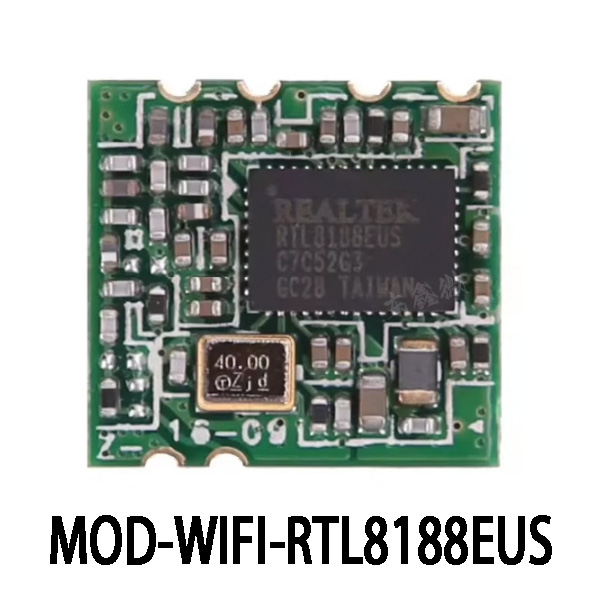
| Parameter | RTL8188EUS-VH-CG | RTL8188EUS-CG | RTL8188ETV-CG | MOD-WIFI-RTL8188EUS |
|---|---|---|---|---|
| Package Type | LQFN-46-EP | LQFN-46-EP | LQFN-46-EP | USB Module |
| Package Size | 4.5 × 6.5 mm | 4.5 × 6.5 mm | 4.5 × 6.5 mm | Approx. 20 × 15 mm |
| Supported Standard | 802.11 b/g/n (1T1R) | 802.11 b/g/n (1T1R) | 802.11 b/g/n (1T1R) | 802.11 b/g/n (1T1R) |
| Max Data Rate | 150 Mbps | 150 Mbps | 150 Mbps | 150 Mbps |
| Interface Type | USB 2.0 | USB 2.0 | USB 2.0 | USB 2.0 (Integrated connector) |
| Security Protocols | WEP/TKIP/AES/WPA/WPA2/WAPI | WEP/TKIP/AES/WPA/WPA2/WAPI | WEP/TKIP/AES/WPA/WPA2 | WEP/TKIP/AES/WPA/WPA2 |
| Antenna Type | Single Antenna | Single Antenna | Single Antenna | Internal PCB Antenna or External Optional |
| Remarks | Original model | Fully compatible, minor naming difference | Minor differences in batch/certification | Integrated module, compact, easy to use |
If you’re replacing the RTL8188EUS-VH-CG, the RTL8188EUS-CG and RTL8188ETV-CG are pin-to-pin compatible—just double-check drivers and certifications, as batches may vary slightly. Or, you can try the MOD-WIFI-RTL8188EUS module. It’s easy to use since it comes with built-in antenna and connectors, but it’s bulkier and pricier, requiring PCB adjustments. Simply put, the module is perfect for quick prototypes, while the chip versions suit mass production better.
RTL8188EUS-VH-CG USB WiFi Circuit Example
More Like This

MC5430F
Motorola

JD54LS51BCA
National Semiconductor

USPLSI2032VE-110LB49
Lattice Semiconductor Corporation
74S22PC
Rochester Electronics, LLC

9504DC
National Semiconductor

9005PC
National Semiconductor

9007DC
National Semiconductor
9004DC
National Semiconductor

SN74HC804DWR
Texas Instruments
SN700863DWR
Texas Instruments
4001BDMQB
National Semiconductor
54F02FMQB
National Semiconductor
Also Add to Cart

MAX6323HUT46
Analog Devices Inc./Maxim Integrated
1621B2UZZGR
Texas Instruments

74AUP2G34GXZ
Nexperia USA Inc.

MM74HC123ASJX
Fairchild Semiconductor

8N3QV01KG-1053CDI8
Renesas Electronics America Inc

8N4SV76LC-0005CDI
Renesas Electronics America Inc
8N4Q001KG-1135CDI
Renesas Electronics America Inc

74FCT2541CTSOCTE4
Texas Instruments

8N3SV76KC-0039CDI8
Renesas Electronics America Inc

KSZ8081RNACA
Microchip Technology
MCIMX31CVMN4C
Freescale Semiconductor
MAX14599EEWV+T
Analog Devices Inc./Maxim Integrated
Related Products
MC5430F
Motorola
JD54LS51BCA
National Semiconductor
USPLSI2032VE-110LB49
Lattice Semiconductor Corporation
74S22PC
Rochester Electronics, LLC
9504DC
National Semiconductor
9005PC
National Semiconductor
9007DC
National Semiconductor
9004DC
National Semiconductor
SN74HC804DWR
Texas Instruments
SN700863DWR
Texas Instruments
4001BDMQB
National Semiconductor
54F02FMQB
National Semiconductor
DM54S20W/883
National Semiconductor

MC3129L
Motorola
4071BDM
National Semiconductor
MC9814P
Motorola
MC9825P
Motorola

74AC11000NS
Texas Instruments
MC5420L
Motorola
MC5401L
Motorola
MC5401F
Motorola
SN74H61N
Texas Instruments
MC5410F
Motorola
MC5430L
Motorola

SN74AS138N-J
Texas Instruments
CD4023BCN
Fairchild Semiconductor
4019BDC
National Semiconductor
74H40DC
National Semiconductor
5420FMQB
National Semiconductor
4025BDM
National Semiconductor
Please send RFQ , we will respond immediately.

Please send RFQ , we will respond immediately.
Copyright © 2024 All Rights Reserved