
TL082CP pinout, circuit, equivalent, schematic
- Amplifier Type: J-FET
- Number of Circuits: 2
- Output Type: -
- Package: 8-DIP (0.300, 7.62mm)


FREE delivery for orders over HK$250.00

Quick response, quick quotaton

Flash shipment,no worries after sales

Original channel,guarantee of the authentic products
How to make Simple Pre-Subwoofer Powerful Amplifier with TL082CP, New Circuit pre-subwoofer at home
TL082CP
If you’re working with audio gear or maybe setting up some active filters, the TL082CP is a solid choice. It’s got two high-gain amplifiers that are already frequency-compensated, so you won’t have to worry about unstable signals. The low noise design is a big plus, especially when you need precision. It’s also got a wide bandwidth, which is super useful for high-frequency applications. And, since it uses low power, it’s a great fit for battery-powered or portable projects. It can handle a voltage range from ±3V to ±18V, so you’ve got flexibility in your setup. The high slew rate means it reacts quickly to signal changes, and the built-in short-circuit protection gives some peace of mind. Oh, and the high input impedance? That means it won’t mess with your previous circuit stages.
TL082CP Op Amp Pinout Diagram

| Pin Number | Pin Name | Description |
|---|---|---|
| 1 | Offset Null | Used for offset voltage adjustment. |
| 2 | Inverting Input (V-) | Input for the inverting signal. |
| 3 | Non-inverting Input (V+) | Input for the non-inverting signal. |
| 4 | V- (Negative Supply) | Negative supply voltage input. |
| 5 | Offset Null | Used for offset voltage adjustment. |
| 6 | Output | Output of the operational amplifier. |
| 7 | V+ (Positive Supply) | Positive supply voltage input. |
| 8 | NC (No Connection) | This pin is not connected internally. |
The TL082CP is a dual op-amp, which means it houses two op-amps in one package. For each op-amp, you’ll be dealing with pins 2, 3, and 6 for the input and output signals.
Pins 1 and 5 are for offset nulling, a key feature to get rid of any offset voltages, which is especially helpful when working with audio or sensor systems.
Make sure to connect the power supply correctly: Pin 4 for V- and Pin 7 for V+ are where you’ll connect your power sources. You’ll need to follow the recommended voltage range (usually ±3V to ±18V) for proper operation.
Lastly, Pin 8 is unused, so just leave it disconnected. That’s pretty much it for the pinout!
TL082CP Equivalent Op Amp
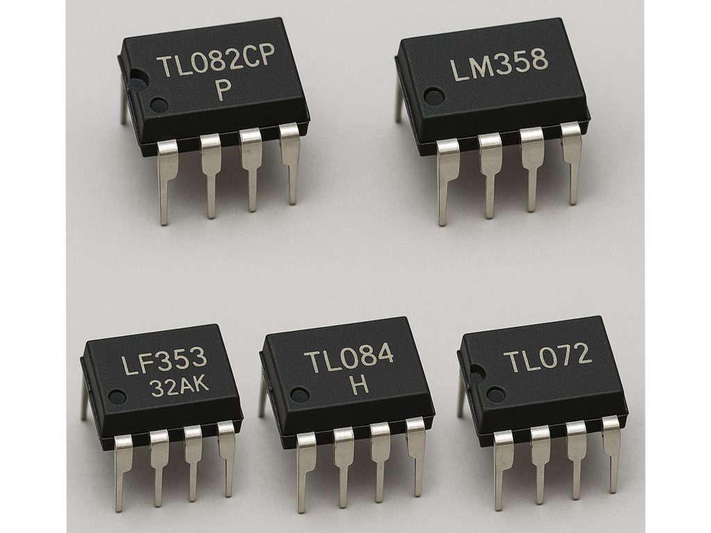
| Feature | TL082CP | LM358 | LF353 | TL084 | TL072 |
|---|---|---|---|---|---|
| Type | Dual Op-Amp | Dual Op-Amp | Dual Op-Amp | Quad Op-Amp | Dual Op-Amp |
| Supply Voltage | ±3V to ±18V | ±3V to ±32V | ±3V to ±18V | ±3V to ±18V | ±3V to ±18V |
| Bandwidth | 3 MHz | 1 MHz | 3 MHz | 3 MHz | 3 MHz |
| Slew Rate | 0.3 V/μs | 0.3 V/μs | 0.7 V/μs | 0.3 V/μs | 0.3 V/μs |
| Input Offset Voltage | 3 mV | 3 mV | 3 mV | 3 mV | 3 mV |
| Power Consumption | Low | Low | Low | Low | Low |
| Package Type | DIP-8, SOIC-8 | DIP-8, SOIC-8 | DIP-8, SOIC-8 | DIP-14, SOIC-14 | DIP-8, SOIC-8 |
| Output Swing | ±10V | ±13V | ±10V | ±10V | ±10V |
| Application | Audio, Signal Processing | General Purpose, Low-Power | High-Fidelity Audio | General Purpose, Low Noise | Audio, Signal Processing |
If you’re thinking about using the LM358, it can definitely replace the TL082CP, but it works with a higher voltage range (up to ±32V), which could be useful in certain circuits. Keep in mind though, it has a lower bandwidth (1 MHz) compared to the TL082CP’s 3 MHz, so it might not perform as well in high-frequency situations like audio processing or active filters.
The LF353 has a higher slew rate (0.7 V/µs), so it might be a better fit for fast signal processing or projects needing more responsiveness. However, it does consume a little more power than the TL082CP, which makes it less ideal for low-power, battery-powered circuits.
All these op-amps have similar pinouts and packaging options, but make sure to compare their specs with your specific needs for the best performance. For audio, the TL072 could be a close match with slightly better low-noise performance.
TL082CP Audio Amplifier Circuit Example

In this circuit, the TL082CP op-amp works in two stages to amplify the audio signal. In the first stage, the input signal (VIN) enters the non-inverting terminal, and the resistors R1 and R2 set the gain. C1 blocks any DC and only lets the audio signal pass. R3 and R4 manage the feedback, stabilizing the first stage.
The output from the first stage feeds into the second op-amp, where similar components (R1′, R2′, C1) boost the signal further, and R3′ and R4′ control the final amplification. This two-stage setup increases the gain, making the output signal stronger for driving speakers or other audio devices.
TL082CP vs NE5532 Sound Comparison
| Parameter | TL082CP | NE5532 |
|---|---|---|
| Type | Dual operational amplifier | Dual operational amplifier |
| Bandwidth | 3 MHz | 8 MHz |
| Slew Rate | 0.3 V/μs | 0.3 V/μs |
| Input Voltage Noise | 8 nV/√Hz | 5 nV/√Hz |
| Input Impedance | 1 MΩ | 100 MΩ |
| Output Swing | ±12V (for ±15V supply) | ±13V (for ±15V supply) |
| Total Harmonic Distortion (THD) | 0.003% | 0.0003% |
| Power Supply Voltage | ±3V to ±18V | ±3V to ±18V |
| Power Consumption | Low (3.5 mA) | Moderate (8 mA) |
For sound quality, the NE5532 is a better choice with its lower Total Harmonic Distortion (THD), making it ideal for high-fidelity audio where clarity is important. The TL082CP, while higher in THD, still works well in less demanding setups. When it comes to noise performance, the NE5532 has lower input voltage noise, which makes it the better option for sensitive audio applications. It also has a wider bandwidth (8 MHz vs. 3 MHz), which is important for higher frequency tasks. However, if you’re looking for something more power-efficient, the TL082CP is the way to go, using half the current of the NE5532. In conclusion, if you need superior sound and low noise, the NE5532 is your pick. But, if low power consumption matters more or you’re working with less demanding audio circuits, the TL082CP is a good alternative.
TL082CP Buffer Circuit for Analog Signals
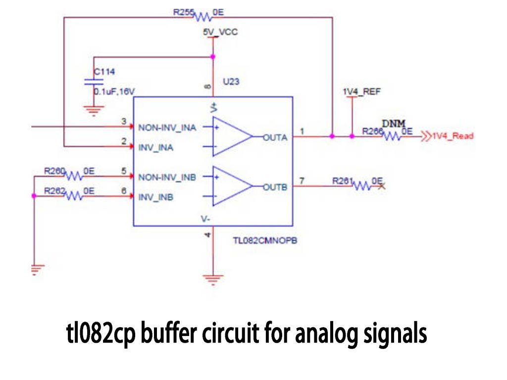
This circuit uses the TL082CP op-amp as a buffer for analog signals. It’s set up as a voltage follower, meaning the output exactly follows the input with no amplification (gain of 1). The inverting input (INV_INB) is connected to the output, while the non-inverting input (NON_INV_INB) receives the signal you want to buffer.
The resistors (R260, R262, R281) and capacitor (C114) work together to stabilize the circuit, filter the power supply, and control the frequency response. The capacitor especially helps with high-frequency performance and noise reduction.
As for replacing the TL082CMNOPB with the TL082CP, you’re good to go. They’re essentially the same op-amp family, with the main difference being the package type. The performance won’t change, and the TL082CP will work just fine as a drop-in replacement.
TL082CP Low Noise Amplifier Project
Here’s a simple low-noise amplifier project using the TL082CP op-amp. The goal is to amplify weak analog signals—like those from a microphone or sensor—without adding much noise, making it perfect for audio, RF, or instrumentation applications.
For the components, you’ll need the TL082CP op-amp, resistors to set the gain, and capacitors to filter the power supply and stabilize the signal. You’ll power it with a ±5V or ±15V supply, depending on your design. The circuit is set up as a non-inverting amplifier, which amplifies the signal without changing its polarity. Resistors R1 and R2 will control the gain, and the capacitors will help with noise reduction.
This design is low-power, performs well with weak signals, and will give you a solid amplifier for your project.
More Like This

TLV2474CDR
Texas Instruments

LMP8278QMM/NOPB
Texas Instruments

TSC2010IST
STMicroelectronics

AD8663ACPZ-REEL7
Analog Devices Inc.

AS2333QS-13
Diodes Incorporated

OPA2330AIDRBT
Texas Instruments

ISL28233FRZ
Renesas Electronics America Inc

TS512BIYDT
STMicroelectronics

OPA2322SAIDGST
Texas Instruments

LMV852MME/NOPB
Texas Instruments
LMV852MM/NOPB
Texas Instruments

EL5174ISZ
Renesas Electronics America Inc
Also Add to Cart
RC4580IP
Texas Instruments

INA210AIDCKR
Texas Instruments

AD711JRZ
Analog Devices Inc.

OPA227UA/2K5
Texas Instruments

OP113ESZ-REEL7
Analog Devices Inc.

MAX4230AXK+T
Analog Devices Inc./Maxim Integrated

OPA209AIDBVR
Texas Instruments

INA281A3QDBVRQ1
Texas Instruments

OP184ESZ
Analog Devices Inc.
OPA2171AQDRQ1
Texas Instruments

LM4562MAX/NOPB
Texas Instruments

LMV105M7X
National Semiconductor
Related Products
TLV2474CDR
Texas Instruments
LMP8278QMM/NOPB
Texas Instruments
TSC2010IST
STMicroelectronics
AD8663ACPZ-REEL7
Analog Devices Inc.
AS2333QS-13
Diodes Incorporated
OPA2330AIDRBT
Texas Instruments
ISL28233FRZ
Renesas Electronics America Inc
TS512BIYDT
STMicroelectronics
OPA2322SAIDGST
Texas Instruments
LMV852MME/NOPB
Texas Instruments
LMV852MM/NOPB
Texas Instruments
EL5174ISZ
Renesas Electronics America Inc

LTC2050CS6#TRMPBF
Analog Devices Inc.
MAX4452EUK+T
Analog Devices Inc./Maxim Integrated
OPA210IDBVT
Texas Instruments

LT1803CS5#TRMPBF
Analog Devices Inc.
OPA191IDGKT
Texas Instruments
INA293B4QDBVRQ1
Texas Instruments
INA293A1QDBVRQ1
Texas Instruments

OPA334AIDBVT
Texas Instruments
LMP8481MME-H/NOPB
Texas Instruments
TS27L2CD
STMicroelectronics
OPA838IDCKR
Texas Instruments
OPA251UA/2K5
Texas Instruments
LM7341MFE/NOPB
Texas Instruments
OPA145IDGKT
Texas Instruments

LTC2063ISC6#TRMPBF
Analog Devices Inc.

TSU112IYQ3T
STMicroelectronics

MAX4489AUA+T
Analog Devices Inc./Maxim Integrated
TLV2464CDR
Texas Instruments
Please send RFQ , we will respond immediately.
