
UA741CP pinout, circuit & datasheet
- Amplifier Type: General Purpose
- Number of Circuits: 1
- Output Type: -
- Package: 8-DIP (0.300, 7.62mm)


FREE delivery for orders over HK$250.00

Quick response, quick quotaton

Flash shipment,no worries after sales

Original channel,guarantee of the authentic products
How to get working UA741CP IC? (2 Solutions!!)
UA741CP
If you’ve done analog circuits, you’ve probably used the UA741CP op-amp. It’s been popular for decades because it’s affordable, reliable, and easy to find. It accepts single (5~30V) or dual (±15V) power supplies, and you can fine-tune offset voltage using two external pins. With about 1MHz bandwidth, it handles most low-frequency signals nicely. Plus, it comes with built-in short-circuit protection, and its DIP-8 package is perfect for breadboard experiments.
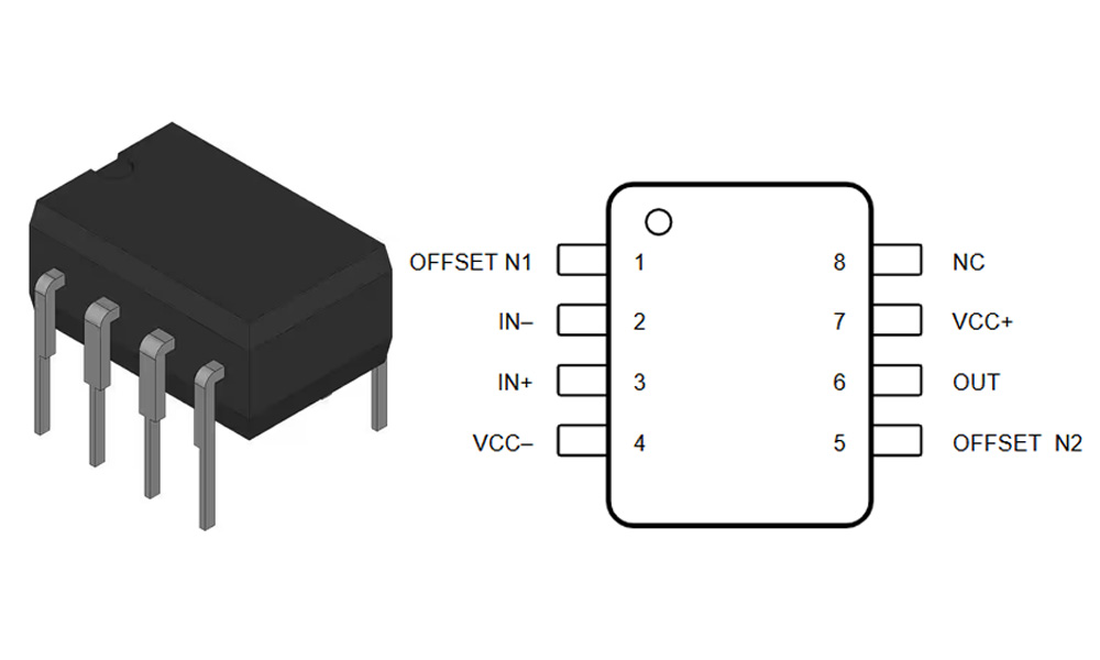
UA741CP Pinout
| Pin Number | Name | Function Description |
|---|---|---|
| 1 | Offset Null | Input offset voltage adjustment (used with Pin 5) |
| 2 | Inverting (−) | Inverting input |
| 3 | Non-Inverting (+) | Non-inverting input |
| 4 | V− (VEE) | Negative power supply input or ground |
| 5 | Offset Null | Input offset voltage adjustment (used with Pin 1) |
| 6 | Output | Output terminal |
| 7 | V+ (VCC) | Positive power supply input |
| 8 | NC | No connection (not internally connected) |
When wiring up a UA741CP, pins 2 and 3 handle your differential input signals, and your output comes from pin 6. Pins 4 (-) and 7 (+) connect to your ±12V or ±15V power supplies. Pins 1 and 5 are optional—leave them disconnected if precision isn’t critical, or add a potentiometer if you need offset adjustment. Its DIP-8 package fits neatly into breadboards or PCBs. Just avoid pushing the output too close to the supply rails, as distortion might occur.
UA741CP Equivalent
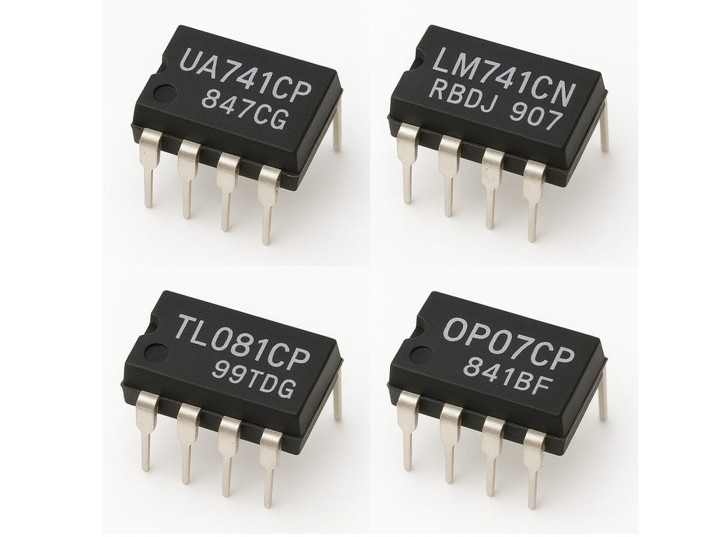
| Parameter / Model | UA741CP | LM741CN | TL081CP | OP07CP |
|---|---|---|---|---|
| Package | DIP-8 | DIP-8 | DIP-8 | DIP-8 |
| Operating Voltage Range | ±3V ~ ±18V | ±3V ~ ±22V | ±3V ~ ±18V | ±3V ~ ±18V |
| Gain Bandwidth Product (GBW) | 1 MHz | 1 MHz | 3 MHz | 0.6 MHz |
| Typical Slew Rate | 0.5 V/μs | 0.5 V/μs | 13 V/μs | 0.3 V/μs |
| Input Offset Voltage | ≤ 6 mV | ≤ 6 mV | ≤ 3 mV | ≤ 75 μV (more precise) |
| Input Bias Current | 80 nA | 80 nA | 100 pA (lower) | 2 nA |
| Unity Gain Stable | Yes | Yes | Yes | Yes |
If you can’t find a UA741, the LM741CN is your easiest drop-in replacement—it’s practically identical. The TL081CP is another good choice but with JFET inputs, providing higher speed and lower input current, ideal for faster applications. OP07CP is best if you need low offset voltage for precision circuits, though it’s slower. Always consider slew rate, input current, and bandwidth carefully before swapping chips.
UA741CP Amplifier Circuit Example
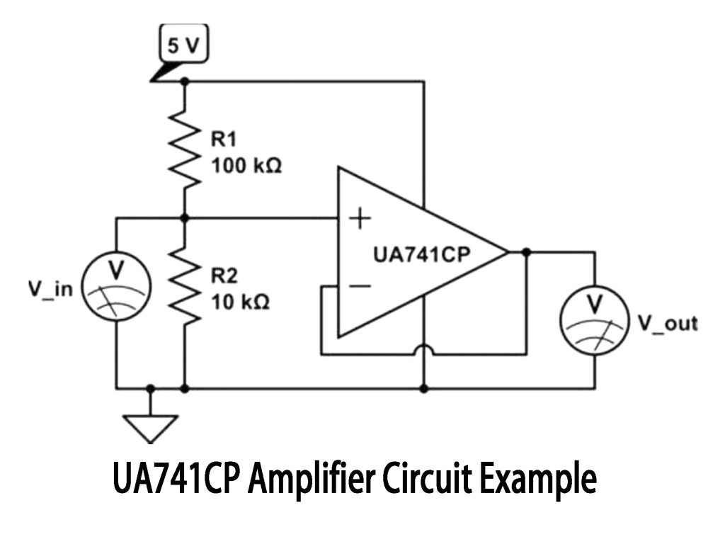
This circuit you see is a simple non-inverting amplifier using UA741CP. Your input signal connects to the positive input of the op-amp, while two resistors (R1 and R2) create negative feedback on the negative input to control gain. With R1=100kΩ and R2=10kΩ, your output gain is about 11 (1+100kΩ/10kΩ). So, an input of 0.2V gives around 2.2V output. Always use ± dual power supply for clean results and avoid distortion.
UA741CP Inverting Amplifier Wiring
When wiring UA741CP as an inverting amplifier, just connect your input signal to the negative input pin through an input resistor (Rin). Use a feedback resistor (Rf) from output back to the negative input, and ground the positive input pin. The gain is simply -Rf/Rin. For instance, Rf=100kΩ, Rin=10kΩ gives you a gain of -10. Remember, use a ±15V dual power supply to achieve proper negative output voltage, ideal for audio or sensor signals.
UA741CP Comparator Circuit Design
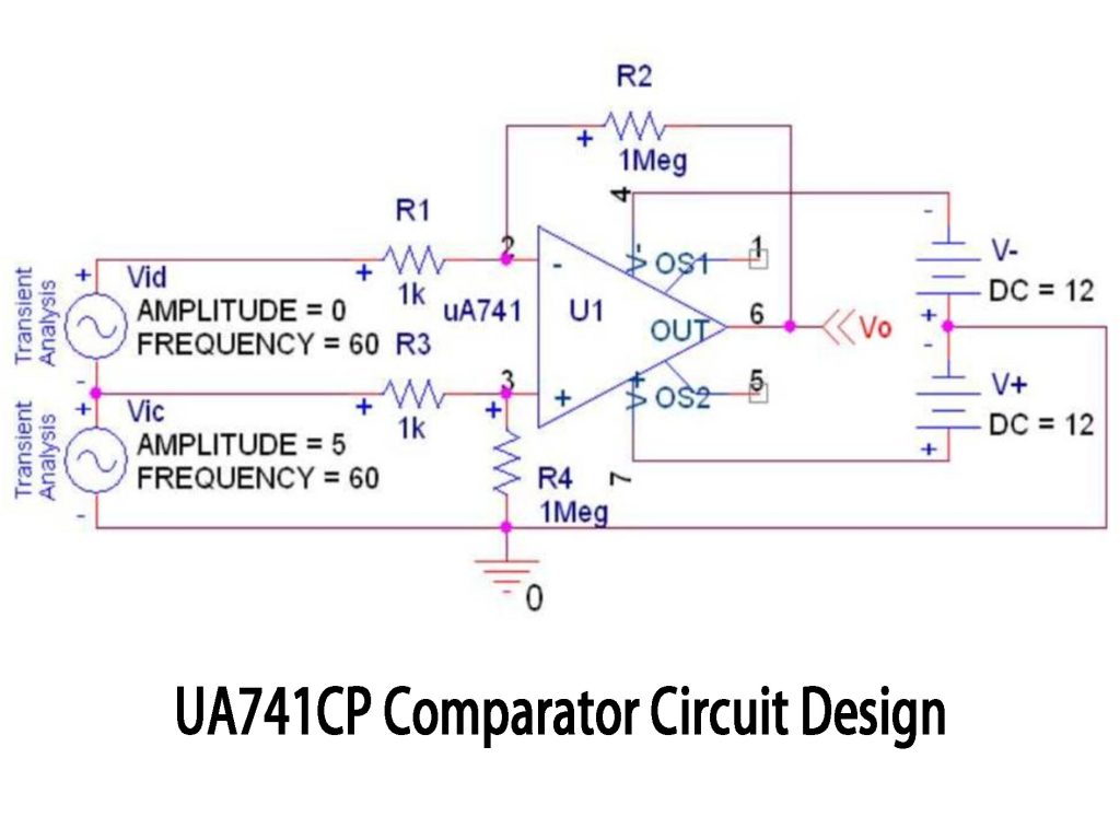
You might think UA741 is just for amplification, but it also works nicely as a basic comparator. In this circuit, your two input voltages connect to the op-amp inputs. When Vic (positive input) exceeds Vid (negative input), the output swings to about +12V; otherwise, it goes down to -12V. Adding resistor R2 provides hysteresis, preventing jitter around the switching point. While UA741 isn’t suitable for high-speed precision comparisons, it’s great for simpler tasks like voltage threshold detection or battery monitoring.
UA741CP Audio Preamp Project
If you’ve got a UA741CP lying around, building an audio preamp for your mic or guitar is straightforward. Just feed your audio signal into the positive input and use two resistors (like 100kΩ and 10kΩ) to set a gain of about 11x. Use coupling capacitors (1~10μF) on input and output to block DC. Power it with ±12V or ±15V for better audio range. For condenser mics, add a simple transistor stage upfront. Need even cleaner sound? Consider upgrading to TL072 or NE5532 op-amps.
More Like This

MC5430F
Motorola

JD54LS51BCA
National Semiconductor

USPLSI2032VE-110LB49
Lattice Semiconductor Corporation
74S22PC
Rochester Electronics, LLC

9504DC
National Semiconductor

9005PC
National Semiconductor

9007DC
National Semiconductor
9004DC
National Semiconductor

SN74HC804DWR
Texas Instruments
SN700863DWR
Texas Instruments
4001BDMQB
National Semiconductor
54F02FMQB
National Semiconductor
Also Add to Cart

89HPES4T4G2ZBALG
Renesas Electronics America Inc

8N3Q001KG-1075CDI8
Renesas Electronics America Inc
M2S025-1VF256
Microchip Technology

8N4DV85EC-0163CDI8
Renesas Electronics America Inc

74AUP1T1326GT115
NXP USA Inc.

ISL34341INZ
Renesas Electronics America Inc

SN74LVC2244APWT
Texas Instruments

8N4SV75LC-0171CDI
Renesas Electronics America Inc
XC9236A1HC4R-G
Torex Semiconductor Ltd

74LVCH32244AEC/G;5
NXP USA Inc.

BQ7693006DBTR
Texas Instruments
GAL16V8D-10LJN
Lattice Semiconductor Corporation
Related Products
MC5430F
Motorola
JD54LS51BCA
National Semiconductor
USPLSI2032VE-110LB49
Lattice Semiconductor Corporation
74S22PC
Rochester Electronics, LLC
9504DC
National Semiconductor
9005PC
National Semiconductor
9007DC
National Semiconductor
9004DC
National Semiconductor
SN74HC804DWR
Texas Instruments
SN700863DWR
Texas Instruments
4001BDMQB
National Semiconductor
54F02FMQB
National Semiconductor
DM54S20W/883
National Semiconductor

MC3129L
Motorola
4071BDM
National Semiconductor
MC9814P
Motorola
MC9825P
Motorola

74AC11000NS
Texas Instruments
MC5420L
Motorola
MC5401L
Motorola
MC5401F
Motorola
SN74H61N
Texas Instruments
MC5410F
Motorola
MC5430L
Motorola

SN74AS138N-J
Texas Instruments
CD4023BCN
Fairchild Semiconductor
4019BDC
National Semiconductor
74H40DC
National Semiconductor
5420FMQB
National Semiconductor
4025BDM
National Semiconductor
Please send RFQ , we will respond immediately.
