
2N5457 Transistor Pinout & Datasheet PDF
- FET Type: N-Channel
- Current - Drain (Idss) @ Vds (Vgs=0): 1 mA @ 15 V
- Voltage - Breakdown (V(BR)GSS): 25 V
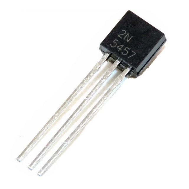
- Package: TO-226-3, TO-92-3 (TO-226AA)


FREE delivery for orders over HK$250.00

Quick response, quick quotaton

Flash shipment,no worries after sales

Original channel,guarantee of the authentic products
Passive Modulation Technique Using a 2N5457 JFET (Add-on Circuit)
2n5457
The 2N5457 is an N-channel JFET, commonly used in analog circuits. If you’re working with low-noise applications, this is a great option. Here’s why:
It has a Vds rating of 25V and can handle up to 20mA of drain current. The gate-source voltage range is from ±20V, while the gate cutoff voltage falls between -0.5V and -6V. With a typical transistor gain of 15 to 75, it’s perfect for applications where you need high input impedance with minimal gate current.
What sets it apart is its low power dissipation of just 500mW, making it ideal for battery-powered or low-power circuits. It comes in a TO-92 package and is widely used in RF and audio amplifiers, as well as switching circuits. So, if you’re designing something that needs low noise and efficiency, this transistor should be on your radar.
2n5457 Pinout
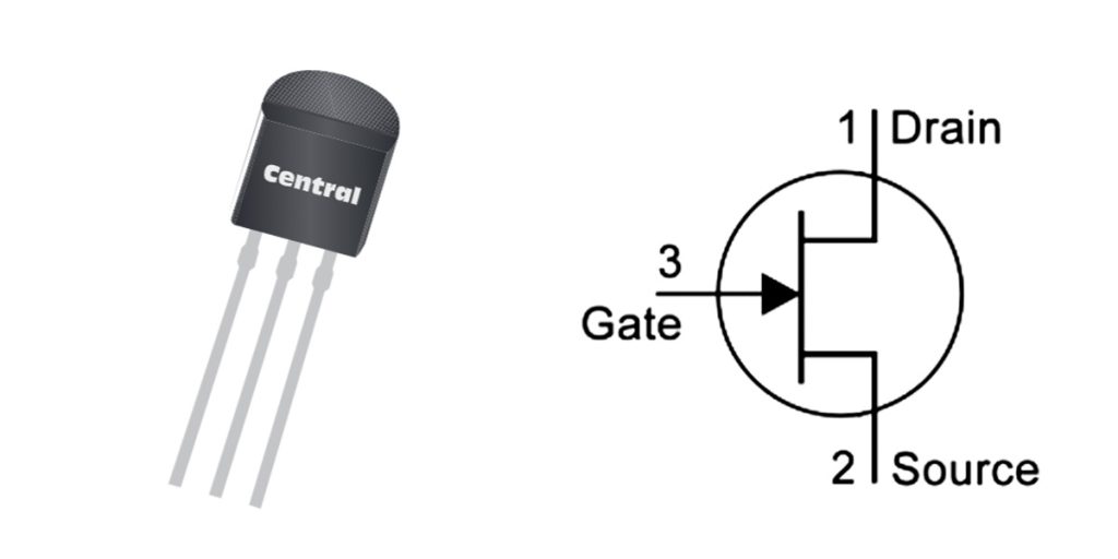
| Pin Number | Pin Name | Function Description |
|---|---|---|
| 1 | Source | Controls the current flow direction, connected to the negative side of the load. |
| 2 | Drain | Current flows through this pin, typically connected to the load and power supply. |
| 3 | Gate | Controls the switching state of the device, typically connected to the input signal source. |
When using the 2N5457, here’s what you need to keep in mind for each pin:
Source (Source Pin): This is the input side of the JFET. It’s typically connected to the negative side of your circuit, like ground or a low-voltage point. The voltage here controls whether the transistor is on or off.
Drain (Drain Pin): This is where the current flows out of the transistor. It connects to the positive voltage of the power supply or to your load. The difference in voltage between the source and drain will determine how the transistor behaves.
Gate (Gate Pin): This controls the flow of current between the source and drain. To turn the transistor on or off, you apply a negative voltage (for an N-channel JFET) to the gate. Make sure the gate voltage doesn’t exceed the recommended range (usually ±20V), as too high a voltage could damage the transistor.
For low-noise applications, the 2N5457 is a solid choice, but always consider impedance matching in your circuit for the best performance.
2n5457 Equivalent
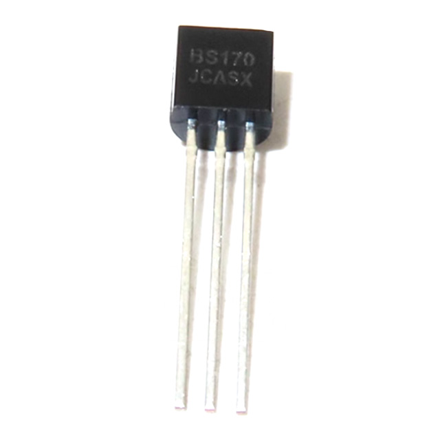
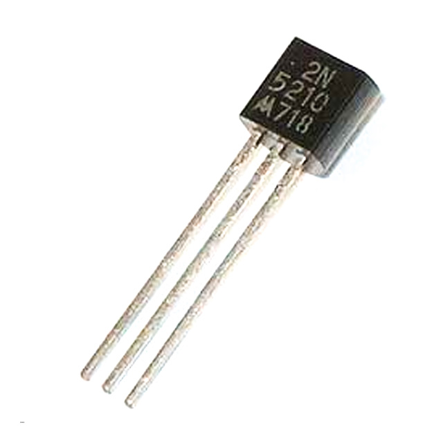
| Parameters | 2N5457 | 2N5458 | J112 | BS170 | 2N5210 |
|---|---|---|---|---|---|
| Package Type | TO-92 | TO-92 | TO-92 | TO-220 | TO-92 |
| Source-Drain Voltage (Vds) | 25V | 25V | 30V | 60V | 25V |
| Gate-Source Voltage (Vgs(off)) | -0.5V to -6V | -0.5V to -6V | -0.5V to -6V | -2V | -0.5V to -6V |
| Drain Current (Id) | 20mA (max) | 20mA (max) | 30mA (max) | 200mA (max) | 30mA (max) |
| Gain (gfs) | 15-75mS | 10-50mS | 5-35mS | 4-12mS | 15-50mS |
| Power Dissipation (Pd) | 500mW | 500mW | 500mW | 500mW | 500mW |
| Application Area | Common module circuits, audio applications | Common module circuits, audio applications | Power switches, large signal | Power switches, low-power circuits | Common audio circuits, low-voltage applications |
When choosing a replacement for the 2N5457, here are some things to keep in mind:
Package Type: Most replacements come in a TO-92 package, but models like the BS170 use a TO-220 package. So, you may need to adjust your circuit design accordingly.
Voltage and Current Ratings: Make sure the replacement has the right Vds and Id for your application, especially if you’re working with high-voltage circuits.
Gain: Replacement models might have different gain values, which can impact amplifier performance, especially in audio or RF circuits.
Power Dissipation: All models dissipate 500mW, so they’re fine for low-power applications, but be mindful of your heat management.
Always double-check that the replacement meets your circuit’s specific needs, especially for high-precision designs.
2n5457 Preamplifier Circuit
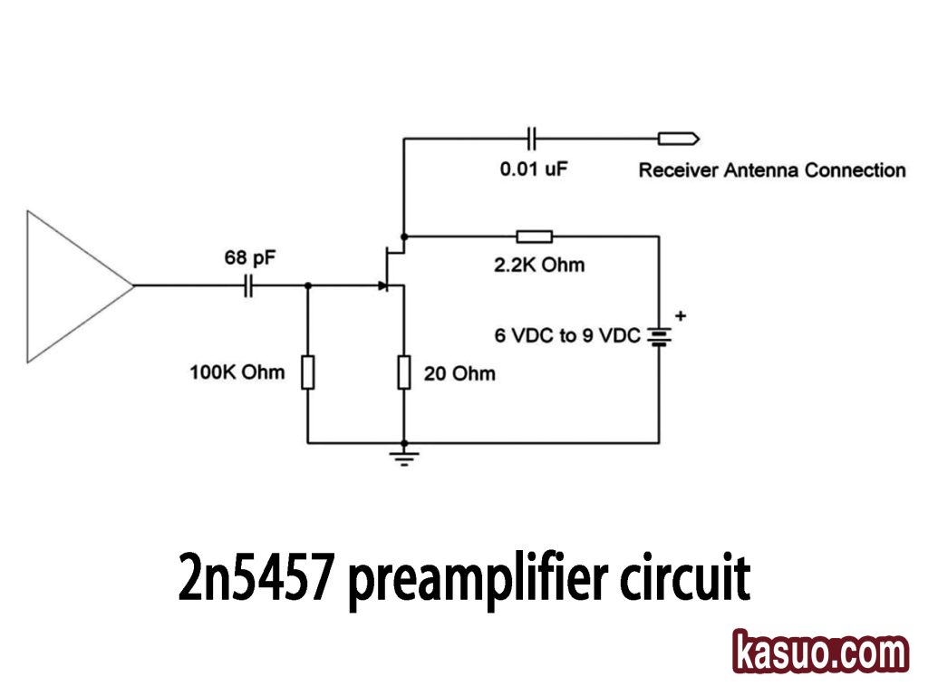
This simple radio receiver circuit is designed to pick up radio signals and process them. Here’s how it works:
The antenna captures radio signals and converts them into electrical signals. The 68pF capacitor is used to tune the circuit to a specific frequency, like the FM band. The 0.01uF capacitor filters out unwanted noise for a cleaner signal. The 2.2K resistor controls the current to adjust the gain, while the 100K resistor limits the input signal to protect the circuit. The 20Ω resistor ensures current is kept within safe limits.
With a 6V to 9V DC power source, the circuit efficiently receives and processes radio signals, making it ready for further amplification or processing.
2n5457 Audio Preamp Application
Here’s a quick rundown of how different preamp circuits work using the 2N5457 transistor:
-
Guitar Preamp: The 2N5457 boosts the weak signal from your guitar pickup, making it strong enough for the power amp. Its high input impedance ensures your tone stays intact, while its low noise keeps your sound clear.
-
Microphone Preamp: Microphones pick up weak signals that need amplifying. The 2N5457’s low noise makes it perfect for capturing all the details without adding unwanted hiss, making it ideal for recording or live sound.
-
Pickup Preamp: Whether it’s an electric piano or electronic drums, the 2N5457 boosts those weak signals without distortion, ensuring clear, noise-free audio for the next stage of processing.
2n5457 Guitar Pedal Booster Circuit
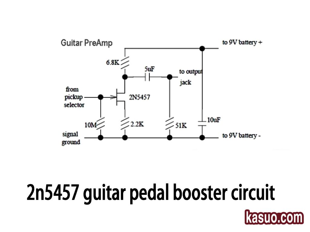
This is a guitar preamp circuit using the 2N5457 N-channel JFET, designed to amplify the weak signal from your guitar pickup. Here’s how it works:
The guitar signal enters through a 10M resistor, which prevents the signal from overloading. The 2N5457 transistor then amplifies the signal. Capacitors (5uF and 10uF) filter the DC components and stabilize the power supply. The circuit’s resistors set the biasing and gain, ensuring smooth performance.
The output signal goes to a jack, ready to connect to an amplifier. With low noise and clear sound, this circuit preserves your guitar’s natural tone and works great for audio applications.
2n5457 Low Noise Jfet Usage
The 2N5457 is a low-noise N-channel JFET, perfect for various applications where high input impedance and low noise are crucial. Here are a few places it shines:
-
Audio Pre-Amps: Its low noise and high impedance make it ideal for amplifying guitar or microphone signals while keeping the sound clear and pure.
-
RF Amplifiers: It excels in radio frequency applications, amplifying signals without adding noise.
-
Radio Receivers: Perfect for boosting weak radio signals in devices like FM receivers.
-
Sensor Interfaces: Ideal for amplifying signals from sensors like temperature or light sensors, ensuring accuracy.
-
Battery-Powered Devices: Its low power consumption makes it great for portable devices, extending battery life while maintaining performance.
The 2N5457 is a go-to choice when you need precision, clarity, and efficiency in low-noise environments.
2n5457 Smd Version
Here’s why SMD versions of components are so useful:
First, they’re smaller – surface-mount packages save space, letting you design more compact and efficient PCBs. This can be a game-changer when you’re working with limited board space.
Second, they’re great for automation – SMD components are perfect for automated pick-and-place machines, which makes them ideal for large-scale production. So, if you’re aiming for fast, efficient manufacturing, SMD is definitely the way to go.
2n5457 Current Limiting Circuit

Let’s break down how this circuit works:
The 2N5457 (Q2) acts as a current limiter. When the current reaches a certain threshold, it adjusts to limit the flow, preventing overload. The operational amplifier compares the input signal with a reference voltage (V_ref) and controls Q2’s gate voltage, thus controlling the current.
Resistors R1 to R4 help regulate current, set bias, and protect the circuit by limiting output current. Diodes protect the circuit from excessive current that could damage components.
This setup is perfect for applications like LED drivers or sensor circuits, where current control is crucial to prevent damage.
More Like This

J5C145MU0/T0BC7DUP
NXP USA Inc.
J5A080GHN/T0BG208Z
NXP USA Inc.
J5A080GHN/T0BG2084
NXP USA Inc.
J3E145GXS/S0BGCA5J
NXP USA Inc.
J3E120GA6/S0BGEA2J
NXP USA Inc.
J3E082EUA/S0BE503V
NXP USA Inc.
J3E082EA6/S0BE547J
NXP USA Inc.
J3E082EA6/S0BE503J
NXP USA Inc.
J3E082EA4/S0BE5AQJ
NXP USA Inc.
J3E081GXS/S1AGCK7J
NXP USA Inc.
J3E081CA4/S1ACH49J
NXP USA Inc.
Also Add to Cart

2N3955A
Harris Corporation
MV2N4858UB/TR
Microchip Technology

SST4119 SOT-23 3L
Linear Integrated Systems, Inc.
,TO-226_straightlead.jpg "2N5953")
2N5953
Central Semiconductor Corp
MV2N4392UB
Microchip Technology

SST5461-T1-E3
Vishay Siliconix
BF510
NXP USA Inc.

2SK3666-2-TB-E
onsemi

PN4393
NTE Electronics, Inc

LSK589 SOIC 8L
Linear Integrated Systems, Inc.
MV2N5114UB/TR
Microchip Technology

PN4092_D27Z
onsemi
Related Products
J5C145MU0/T0BC7DUP
NXP USA Inc.
J5A080GHN/T0BG208Z
NXP USA Inc.
J5A080GHN/T0BG2084
NXP USA Inc.
J3E145GXS/S0BGCA5J
NXP USA Inc.
J3E120GA6/S0BGEA2J
NXP USA Inc.
J3E082EUA/S0BE503V
NXP USA Inc.
J3E082EA6/S0BE547J
NXP USA Inc.
J3E082EA6/S0BE503J
NXP USA Inc.
J3E082EA4/S0BE5AQJ
NXP USA Inc.
J3E081GXS/S1AGCK7J
NXP USA Inc.
J3E081CA4/S1ACH49J
NXP USA Inc.
J3D081YXV/T1AY5E4J
NXP USA Inc.
J3D081YXU/T1AY5E4J
NXP USA Inc.
J3D081VXU/T1AV5ADJ
NXP USA Inc.
J3D016YXV/T1AY599J
NXP USA Inc.
J3D016YXU/T1AY599J
NXP USA Inc.
J3C145CX1/T0BC776J
NXP USA Inc.
J3C145CX1/T0BC732J
NXP USA Inc.
J3C145CUA/T0BC792V
NXP USA Inc.
J3A081GUA/T1AG8VYV
NXP USA Inc.
J2E120EUA/S0BE3A4V
NXP USA Inc.
J2E082EXS/S0BE3B4J
NXP USA Inc.
J2E081GXS/S1AGC34J
NXP USA Inc.
J2E081GXS/S1AGC32J
NXP USA Inc.
J2A012ZXZ/S1AZ3CHJ
NXP USA Inc.
J2A012ZXZ/S1AZ312J
NXP USA Inc.
J2A012ZXZ/S1AZ197J
NXP USA Inc.
J2A012ZXY/S1AZ312J
NXP USA Inc.
J2A012ZXY/S1AZ197J
NXP USA Inc.
Please send RFQ , we will respond immediately.
