
2N7002K | Datasheet, Price, PDF Rectron USA
- FET Type: N-Channel
- Drainto Source Voltage(Vdss): 60 V
- Current-Continuous Drain(Id)@25°C: 300mA (Ta)
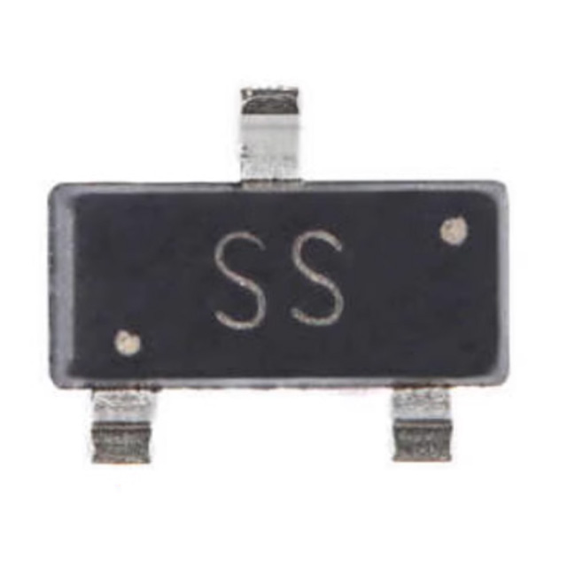
- Package: SOT-23


FREE delivery for orders over HK$250.00

Quick response, quick quotaton

Flash shipment,no worries after sales

Original channel,guarantee of the authentic products
2N7002K 2N7002K-13 N-channel MOSFET chip for Antminer S19K PRO C76 A113D control board
2n7002k
If you’re looking for a compact and efficient MOSFET for your electronics projects, the 2N7002K is a solid choice. It’s an N-channel MOSFET in a tiny SOT-23 surface-mount package, perfect when your PCB space is tight.
It handles voltages up to 60V and currents up to 300mA, making it ideal for controlling low-power loads. Plus, it’s designed specifically for logic-level control, which means you can easily drive it with microcontrollers or logic ICs—no complicated setups needed.
With a gate threshold around 2.0V and low on-resistance (typically less than 2Ω), you’ll get less power wasted as heat and better efficiency. Its high-speed switching capability is great for high-frequency logic circuits, GPIO switching, or voltage-level shifting.
Overall, the 2N7002K works well in portable electronics, simple microcontroller circuits, and basic power management tasks—giving your designs both reliability and performance.
2n7002k Pinout Configuration
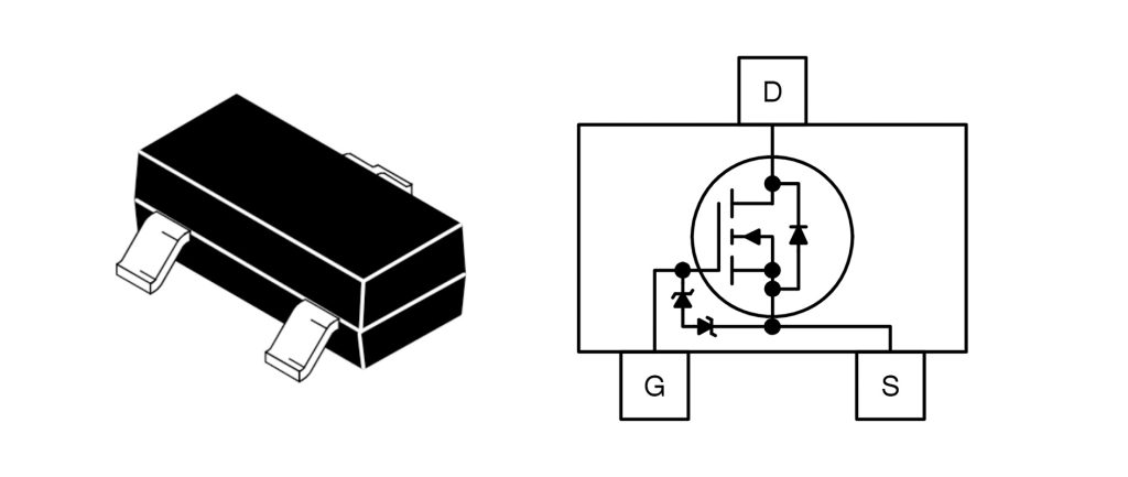
| Pin Number | Pin Name | Function Description |
|---|---|---|
| 1 | Gate (G) | Controls the MOSFET switching state |
| 2 | Source (S) | Usually connected to ground or negative terminal of load |
| 3 | Drain (D) | Connected to the load or positive terminal of power supply |
Pin Usage and Precautions:
When you’re using a 2N7002K MOSFET, here’s what you need to know. Connect the Gate pin to your logic-level signal (like from a microcontroller) to easily control switching. Typically, you’ll attach the Drain pin to your load or positive voltage source, while the Source usually goes to ground or the negative side of your load.
Be careful with static electricity—it can damage the MOSFET, so always handle it carefully and take proper anti-static precautions. Lastly, never exceed its rated limits: keep voltage under 60V and current below 300mA to avoid permanently damaging the component.
Pin Connection Example:
Gate (G): Connect this to your control signal, like from a microcontroller GPIO pin. To keep your MOSFET safe from voltage spikes, it’s smart to add a resistor (around 100Ω to 1kΩ) in series.
Source (S): Usually goes straight to ground (GND). If you’re using the MOSFET as a low-side switch, just tie the source directly to ground.
Drain (D): Connect this pin to the higher side of your load, such as a relay coil, LED, or buzzer. When the MOSFET switches on, it completes the circuit, powering your device.
2n7002k Equivalent Smd Mosfet & 2n7002k Transistor Connection


| Parameter / Model | 2N7002K | BSS138 | BSS123 | DMN601K |
|---|---|---|---|---|
| Polarity | N-channel | N-channel | N-channel | N-channel |
| Package | SOT-23 | SOT-23 | SOT-23 | SOT-23 |
| Max Drain-Source Voltage (VDS) | 60 V | 50 V | 100 V | 60 V |
| Max Drain Current (ID) | 300 mA | 220 mA | 170 mA | 280 mA |
| Gate Threshold Voltage (Vth) | 2.0 V (typ.) | 1.5 V | 2.0 V | 2.1 V |
| On-Resistance (RDS(on)) | ≤ 2 Ω | ≤ 3.5 Ω | ≤ 6 Ω | ≤ 2 Ω |
| Power Dissipation (PD) | 350 mW | 225 mW | 360 mW | 350 mW |
When choosing a replacement MOSFET for your 2N7002K, keep an eye on three main specs: the max drain voltage (Vds), max drain current (Id), and the on-resistance (Rds(on)). Pick a model that’s similar or better in these areas to ensure reliable performance. Also, pay close attention to the gate threshold voltage (Vth)—choose one close to your original, so your circuit will respond correctly to your logic signals. Finally, double-check the replacement MOSFET’s package type and pin arrangement; matching them exactly prevents headaches like shorts or soldering mistakes when you’re swapping components on your PCB.
2n7002k Mosfet Circuit Example

If you’re connecting devices with different logic levels (like 3.3V to 5V), a simple MOSFET-based level shifter like this is ideal. The 2N7002 MOSFET, along with two 10kΩ pull-up resistors (R1 and R2), makes this possible. When your 3.3V side (Net1) goes low, the MOSFET conducts and pulls the 5V side (Net2) low, matching the signals. When Net1 is high, the MOSFET turns off, and Net2 rises to 5V through the resistor. This works both ways, making it perfect for protocols like I²C or UART. Just remember, both sides must share a common ground for reliable signal conversion.
2n7002k Gate Voltage Threshold
When using the 2N7002K MOSFET, the gate threshold voltage (Vth) is important—it tells you how much voltage you need to switch it from off to on. Typically, around 2.0V is enough to activate this MOSFET, making it perfect for controlling directly from low-voltage logic signals, like a 3.3V GPIO pin from your microcontroller.
But keep in mind, the actual threshold voltage can vary between about 1.0V and 2.5V. So, always give yourself a little safety margin when designing your circuit to ensure consistent performance without needing extra level shifting or complicated driver circuits.
2n7002k as Load Switch
When you’re using a 2N7002K MOSFET as a load switch, you’re essentially controlling whether your load gets power or not. When your MOSFET is switched on, it connects your load to the power supply, allowing current to flow and activating the device. When it’s off, the connection breaks, shutting the load down.
What’s great about the 2N7002K is that its low gate threshold voltage (around 2.0V) lets you directly control it with your microcontroller’s GPIO pins—no complicated circuitry needed. It also has a low on-resistance (typically under 2Ω), meaning less heat generation and better efficiency. Plus, its quick switching speed suits digital controls perfectly, and the small SOT-23 package helps you save precious PCB space.
Just be careful: don’t exceed its 300mA current limit or 60V voltage limit. Use a diode if you’re switching inductive loads (like motors or relays), and always handle it carefully to avoid ESD damage.
2n7002k Arduino Interfacing
If you’re connecting a 2N7002K MOSFET to your Arduino, it’s pretty straightforward. You’d typically hook up your Arduino GPIO pin (like D2) through a resistor (around 220Ω to 1kΩ) to the MOSFET’s gate. Connect the MOSFET’s source pin straight to Arduino’s ground, and place your load (like an LED or relay coil) between the 5V supply and the MOSFET’s drain.
Here’s how it works: when your Arduino outputs a HIGH signal, the MOSFET switches on, connecting the load to power, making it run. When the GPIO is LOW, the MOSFET switches off, disconnecting your load.
You can also use PWM signals from Arduino pins to easily control brightness of LEDs or motor speeds. Plus, it’s handy for shifting signal levels between different voltages (like 3.3V and 5V).
Just remember to always add that gate resistor for protection, stay within the MOSFET’s voltage (60V) and current (300mA) limits, and handle carefully to avoid static damage.
2n7002k High Speed Switching
When you’re using the 2N7002K MOSFET in high-speed switching circuits, there are a few reasons it’s a great choice. It has a very low gate charge (about 1.6 nC) and input capacitance (around 20 pF), so it responds quickly to gate signals. Plus, it turns on and off extremely fast—typically in just about 10 nanoseconds, perfect for high-frequency tasks like PWM dimming or logic-level shifting.
To get the best performance, use a smaller gate resistor (100Ω or less), and keep the PCB trace between the gate and the driver circuit as short as possible—this helps reduce parasitic effects. Also, consider using a dedicated MOSFET driver if you need even faster switching speeds.
But remember, fast switching means more potential for EMI noise, so you might need shielding or filtering. And always watch out for voltage spikes—adding a snubber circuit can protect your MOSFET and ensure reliable operation.
2n7002k Logic Level Operation
If you’re wondering what a Logic Level MOSFET is, it’s basically a MOSFET you can easily switch on using standard logic signals from your microcontroller, like an Arduino or Raspberry Pi. The 2N7002K is a great example—it turns on fully at around 2.0 volts, making it perfect for direct control from 3.3V or 5V GPIO pins without extra circuitry.
Using a logic-level MOSFET simplifies your projects because you don’t need additional driver components, saving you both space and energy. Plus, its compact SOT-23 package makes it ideal for tight PCB layouts, and its fast switching speed means quick, efficient response for controlling LEDs, small motors, or relays.
Just keep a few things in mind: always ensure your GPIO voltage clearly exceeds the MOSFET’s gate threshold (around 2V) to guarantee reliable switching. Don’t exceed the MOSFET’s max current of 300mA, and add a resistor (220Ω to 1kΩ) between your GPIO pin and the gate to protect your microcontroller and control switching speed.
More Like This
~~3.jpg "IRFU9024NPBF")
IRFU9024NPBF
International Rectifier

FDG6335N
onsemi

MMBFJ201
onsemi

IRF3205PBF
International Rectifier

IRFP1405PBF
International Rectifier

IRF3205ZSTRLPBF
International Rectifier

IRFP4229PBF
International Rectifier

IRFB7437PBF
International Rectifier
.jpg "IRLR9343TRPBF")
IRLR9343TRPBF
International Rectifier
IRFP4468PBF
International Rectifier
IRF640NSTRLPBF
International Rectifier

FDS6375
National Semiconductor
Also Add to Cart

NTR4003NT1G
onsemi

FCH104N60F
onsemi

DMP3098LQ-7
Diodes Incorporated

SI4840BDY-T1-GE3
Vishay Siliconix

IRFR6215TRPBF
Infineon Technologies

NTD2955T4G
onsemi

SIR871DP-T1-GE3
Vishay Siliconix

FDT86113LZ
onsemi
IRF2807PBF
Infineon Technologies
SI4425DDY-T1-GE3
Vishay Siliconix

FDD5614P
onsemi

NVMFS6B75NLWFT1G
onsemi
Related Products
IRFU9024NPBF
International Rectifier
FDG6335N
onsemi
MMBFJ201
onsemi
IRF3205PBF
International Rectifier
IRFP1405PBF
International Rectifier
IRF3205ZSTRLPBF
International Rectifier
IRFP4229PBF
International Rectifier
IRFB7437PBF
International Rectifier
IRLR9343TRPBF
International Rectifier
IRFP4468PBF
International Rectifier
IRF640NSTRLPBF
International Rectifier
FDS6375
National Semiconductor
IRFB4332PBF
International Rectifier

IRFP3306PBF
International Rectifier

NVTFS5811NLTAG
onsemi
NVTFS4823NTWG
onsemi
NVD5117PLT4G
onsemi
IRF200S234
Infineon Technologies
.jpg "IRF840PBF")
IRF840PBF
Infineon Technologies

AO4407
Alpha & Omega Semiconductor Inc.

2SK3377-Z-E1-AZ
Renesas Electronics America Inc

NVD5867NLT4G
onsemi
NVMFS5A160PLZWFT1G
onsemi

FDWS9510L-F085
onsemi
FDWS9509L-F085
onsemi
NVTFS5826NLWFTAG
onsemi

AON7401L
Alpha & Omega Semiconductor Inc.
AO4407AL
Alpha & Omega Semiconductor Inc.

AO3407
Alpha & Omega Semiconductor Inc.

CPH3461-TL-W
onsemi
Please send RFQ , we will respond immediately.
