
ATMEGA128A Datasheet, Price, PDF, Arduino
- Brands: Microchip Technology
- Download: -
- Price: inquiry
- In Stock: 6048
- Analog Supply Voltage: -
- I/O Voltage: -
- Data ROM Size: -
- Package: -


FREE delivery for orders over HK$250.00

Quick response, quick quotaton

Flash shipment,no worries after sales

Original channel,guarantee of the authentic products
ATMEGA128A-AU – ATMEL : 8-bit Microcontroller with 128K Bytes In-System Programmable Flash
Atmega128a
If you’re planning to use an ATmega128A microcontroller in your next project, you’ve chosen a powerful, versatile chip. It’s based on an efficient 8-bit AVR RISC architecture and runs at speeds up to 16MHz, executing one instruction per clock cycle, which keeps your applications fast.
It packs 128KB of Flash memory for your programs, 4KB of EEPROM for data storage, and another 4KB of SRAM for temporary calculations. You’ve got plenty of flexibility with 53 programmable I/O pins, an 8-channel 10-bit ADC for accurate analog measurements, and built-in SPI, I²C, and UART interfaces for easy communication.
With multiple clock sources and low-power modes, it’s easy to balance speed and battery life. Plus, its interrupt system helps you handle real-time tasks smoothly. Operating between 2.7V and 5.5V and enduring harsh temperatures from -40°C to 85°C, it’s ideal for industrial and educational projects.
Atmega128a Pinout Diagram
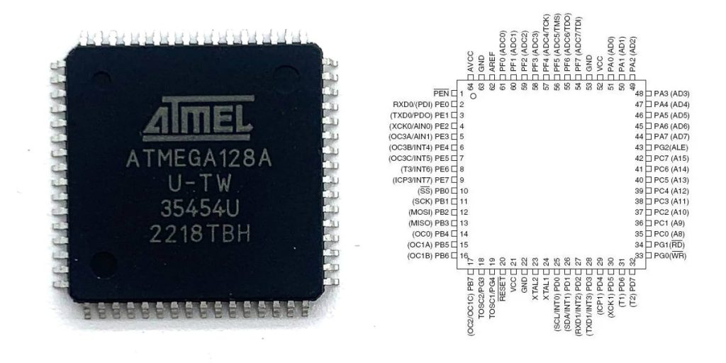
| Pin Number | Pin Name | Description |
| 1 | PEN | Programming Enable, active in ISP programming mode |
| 2 | PE0/RXD0 | USART0 Serial Receive Pin |
| 3 | PE1/TXD0 | USART0 Serial Transmit Pin |
| 4 | PE2/XCK0/AIN0 | USART0 Clock Pin / Analog Comparator Input 0 |
| 5 | PE3/OC3A/AIN1 | Timer Output / Analog Comparator Input 1 |
| 6 | PE4/OC3B/INT4 | Timer Output / External Interrupt Input 4 |
| 7 | PE5/OC3C/INT5 | Timer Output / External Interrupt Input 5 |
| 8 | PE6/T3/INT6 | Timer External Clock / External Interrupt Input 6 |
| 9 | PE7/ICP3/INT7 | Timer Input Capture / External Interrupt Input 7 |
| 10 | VCC | Positive Power Supply (+5V) |
| 11 | GND | Ground (0V) |
| 12 | XTAL2 | External Oscillator Pin |
| 13 | XTAL1 | External Oscillator Input or External Clock Input |
| 14 | PG0/WR | External Memory Write Signal |
| 15 | PG1/RD | External Memory Read Signal |
| 16~23 | PC0~PC7 | Parallel I/O Ports |
| 24 | VCC | Positive Power Supply (+5V) |
| 25 | GND | Ground (0V) |
| 26~33 | PA7~PA0 | Parallel I/O Ports, ADC Analog Input |
| 34~41 | PG2/ALE, PD7~PD0 | ALE External Memory Address Latch Signal, I/O Port |
| 42 | VCC | Positive Power Supply (+5V) |
| 43 | GND | Ground (0V) |
| 44 | PG3 | General I/O Port G3 |
| 45~52 | PB7~PB0 | Parallel I/O Ports, supports SPI interface |
| 53 | AVCC | ADC dedicated power supply (5V) |
| 54 | AREF | ADC reference voltage input |
| 55 | GND | Ground (0V) |
| 56~63 | PF7~PF0 | Parallel I/O Ports, ADC Analog Input |
| 64 | RESET | Chip reset pin, active low |
When you’re wiring up the ATmega128A, there are a few important things to remember. First, make sure your VCC and AVCC pins have a stable 5V supply, and always connect GND pins firmly to ground. To keep ADC readings clean, it’s smart to feed AVCC through an inductor or low-pass filter.
For the XTAL1 and XTAL2 pins, typically you’ll hook up an 8MHz or 16MHz crystal oscillator with matching capacitors. Keep those crystal lines short to avoid interference.
Also, your analog pins (ADC inputs and AREF) need special care. Route these lines away from digital signals to prevent noise messing up your measurements.
Your RESET pin should always have a 10kΩ pull-up resistor connected, to keep your chip from resetting randomly.
Lastly, if you’re using ISP programming, double-check your connections (PEN, MOSI, MISO, SCK, RESET). Make sure nothing else shares those pins during programming, or you could run into trouble.
Atmega128a Equivalent Microcontroller
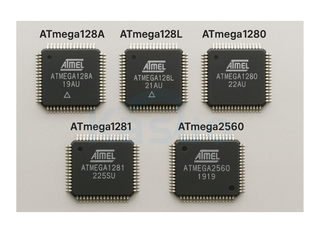
| Parameter | ATmega128A | ATmega128L | ATmega1280 | ATmega1281 | ATmega2560 |
| Architecture | 8-bit AVR RISC | 8-bit AVR RISC | 8-bit AVR RISC | 8-bit AVR RISC | 8-bit AVR RISC |
| Operating Frequency | 16 MHz | 8 MHz | 16 MHz | 16 MHz | 16 MHz |
| Flash Memory Size | 128 KB | 128 KB | 128 KB | 128 KB | 256 KB |
| SRAM Size | 4 KB | 4 KB | 8 KB | 8 KB | 8 KB |
| EEPROM Size | 4 KB | 4 KB | 4 KB | 4 KB | 4 KB |
| ADC Channels | 8-channel 10-bit ADC | 8-channel 10-bit ADC | 16-channel 10-bit ADC | 8-channel 10-bit ADC | 16-channel 10-bit ADC |
| Communication Interfaces | UART, SPI, I²C | UART, SPI, I²C | UART, SPI, I²C | UART, SPI, I²C | UART, SPI, I²C |
| General Purpose I/O Pins | 53 | 53 | 86 | 54 | 86 |
| Operating Voltage | 2.7V ~ 5.5V | 2.7V ~ 5.5V | 2.7V ~ 5.5V | 2.7V ~ 5.5V | 2.7V ~ 5.5V |
| Package | 64-pin TQFP | 64-pin TQFP | 100-pin TQFP | 64-pin TQFP | 100-pin TQFP |
If you’re thinking of swapping out your ATmega128A microcontroller, here are some practical alternatives you can consider.
First, the ATmega128L is a direct pin-compatible match but runs slower (up to 8MHz). It’s great if you’re trying to reduce power consumption and don’t need super-fast speeds.
For something more powerful, ATmega1280 or ATmega2560 could be attractive. They offer more I/O pins, extra SRAM, and more ADC channels—perfect for complex applications. But keep in mind, these come in a larger 100-pin TQFP package, so you’ll have to adjust your PCB layout.
Your easiest upgrade is probably the ATmega1281. It matches your original ATmega128A with the same 64-pin TQFP package but doubles the SRAM to 8KB. It’s ideal if you need extra memory for handling data but don’t want the hassle of changing your PCB layout.
Atmega128a Development Board Circuit
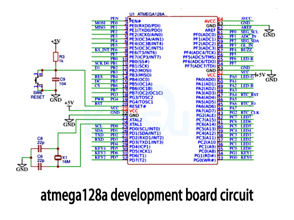
When you’re setting up the ATmega128A, here are some practical tips to keep your circuit running smoothly:
First, your chip uses a single +5V power source. Connect both VCC and AVCC pins to 5V, but for AVCC—which handles analog signals—use a filtering capacitor to keep your ADC measurements accurate and noise-free. Always ground all GND pins securely, and add some decoupling capacitors close to the chip (like C9, C8, and C6) to reduce power supply noise.
For a reliable reset circuit, a simple button (like SW6) paired with a resistor and capacitor works great. Pressing the button briefly pulls the reset line low, resetting your chip neatly.
Use a 16MHz crystal oscillator paired with two 22pF capacitors for a stable external clock source. Clearly label your I/O pins: PE pins handle SPI and UART signals, PB pins run SPI or LCD control, while PC and PD manage I²C and UART interfaces. ADC signals enter through PF pins, perfect for sensors. PA and PG pins neatly connect LEDs and keypads.
Atmega128a Arduino Wiring Example
| ATmega128A Pins | Arduino (Serial Module) Pins | Description |
| VCC (Pin 21, 52) | 5V | Positive Power Supply |
| GND (Pin 22, 53) | GND | Ground |
| XTAL1 (Pin 24) | One end of Crystal Oscillator | External Crystal Oscillator Connection |
| XTAL2 (Pin 23) | Other end of Crystal Oscillator | External Crystal Oscillator Connection |
| RESET (Pin 20) | 10kΩ resistor pull-up to 5V, DTR line with series 0.1µF capacitor (optional) | Reset Pin |
| PE0 (RXD0, Pin 2) | TXD of USB-TTL Module | Serial Data Reception |
| PE1 (TXD0, Pin 3) | RXD of USB-TTL Module | Serial Data Transmission |
If you’re planning to use the ATmega128A with Arduino, here’s a quick tip that’ll save you some headaches:
Start by hooking both VCC pins (21 and 52) of your ATmega128A directly to Arduino’s 5V pin. Do the same with GND (pins 22 and 53), connecting them to Arduino’s ground. For the crystal oscillator, grab a 16MHz crystal and connect it to the XTAL1 and XTAL2 pins. Don’t forget to ground both sides of the crystal through a pair of 22pF capacitors—this step helps stabilize the clock.
The reset circuit’s easy: tie the RESET pin up to 5V with a 10kΩ resistor. If you prefer automatic resets (making uploads easier), take your USB-to-TTL adapter’s DTR line and connect it to RESET through a 0.1µF capacitor.
For the serial communication, remember: RXD pin (PE0) on your microcontroller connects to TXD on the adapter, and TXD pin (PE1) connects back to RXD. Keep these straight, and programming through Arduino IDE will be smooth sailing.
Atmega128a Bootloader Configuration
If you’re planning to use an ATmega128A with Arduino, let me give you a few practical pointers to make things simpler:
First, get your Arduino IDE updated to the latest version. You’ll also need either a USBASP programmer or an Arduino UNO configured as an ISP programmer. Hook up your ATmega128A properly, making sure it’s running with a 16MHz crystal and basic support circuitry.
Next, you’ll want to add MightyCore support. Open the Arduino IDE preferences and add MightyCore’s repository link into the “Additional Boards Manager URLs” section. After installing it, select the ATmega128 board from MightyCore options.
When configuring the bootloader, select the external 16MHz clock option, set the brown-out detection around 2.7 volts, and make sure UART0 is enabled.
Finally, connect your ISP device correctly (MOSI to PE0, MISO to PE1, SCK to PB1, and the RESET pin). Then use the Arduino IDE to burn the bootloader—and you’re good to go!
Atmega128a Projects Tutorial
If you’re just starting out with the ATmega128A microcontroller, here’s a simple project that’ll help you get familiar with setting up pins and controlling digital outputs—lighting up an LED.
Take your LED and notice its legs: the longer leg (positive) goes directly to the PA0 pin on your microcontroller. Connect the shorter leg (negative) to a 220Ω resistor, then to ground. That resistor is crucial—it stops your LED (and your microcontroller) from drawing too much current, protecting them both from damage. Follow these steps, and you’ll easily learn how to turn your LED on and off with code.
example code:
#define LED_PIN PA0 // Define the LED pin as PA0 on ATmega128A
void setup() {
pinMode(LED_PIN, OUTPUT); // Set PA0 as an output pin
}
void loop() {
digitalWrite(LED_PIN, HIGH); // Turn LED on (set pin HIGH)
delay(500); // Wait for 500 milliseconds (0.5 seconds)
digitalWrite(LED_PIN, LOW); // Turn LED off (set pin LOW)
delay(500); // Wait for 500 milliseconds (0.5 seconds)
}
#define LED_PIN PA0
Defines a macro called LED_PIN. From now on, you can use LED_PIN directly in your code to represent the PA0 pin. This improves readability and makes your code easier to maintain.
Void setup()
Runs only once when your microcontroller starts up. It handles the initial setup:
- pinMode(LED_PIN, OUTPUT) sets the defined LED pin as an output. This means the pin will send voltage signals (either HIGH or LOW).
Void loop()
Runs repeatedly, making your LED blink on and off in a continuous loop:
- digitalWrite(LED_PIN, HIGH) sends a high voltage (5V) to the LED pin, turning the LED on.
- delay(500) pauses your program for half a second, keeping the LED on for this duration.
- digitalWrite(LED_PIN, LOW) sends a low voltage (0V) to the LED pin, turning the LED off.
- Another delay(500) pauses again for half a second, keeping the LED off for this duration.
More Like This

MC5430F
Motorola

JD54LS51BCA
National Semiconductor

USPLSI2032VE-110LB49
Lattice Semiconductor Corporation
74S22PC
Rochester Electronics, LLC

9504DC
National Semiconductor

9005PC
National Semiconductor

9007DC
National Semiconductor
9004DC
National Semiconductor

SN74HC804DWR
Texas Instruments
SN700863DWR
Texas Instruments
4001BDMQB
National Semiconductor
54F02FMQB
National Semiconductor
Also Add to Cart
S-8224AAW-I8T1U
ABLIC Inc.

KD82750PB-25
Intel

TLV9002QDRQ1
Texas Instruments
XC9237A1ACER-G
Torex Semiconductor Ltd

NCT5104D
Nuvoton Technology Corporation

8N4DV85BC-0021CDI
Renesas Electronics America Inc

LT1054ISW#PBF
Analog Devices Inc.

NCV7513BFTR2G
onsemi

RT7272BGSP
Score Electronics

DS1685S-5
Analog Devices Inc./Maxim Integrated

SN74V273-15GGM
Texas Instruments

AD7569JRZ
Analog Devices Inc.
Related Products
MC5430F
Motorola
JD54LS51BCA
National Semiconductor
USPLSI2032VE-110LB49
Lattice Semiconductor Corporation
74S22PC
Rochester Electronics, LLC
9504DC
National Semiconductor
9005PC
National Semiconductor
9007DC
National Semiconductor
9004DC
National Semiconductor
SN74HC804DWR
Texas Instruments
SN700863DWR
Texas Instruments
4001BDMQB
National Semiconductor
54F02FMQB
National Semiconductor
DM54S20W/883
National Semiconductor

MC3129L
Motorola
4071BDM
National Semiconductor
MC9814P
Motorola
MC9825P
Motorola

74AC11000NS
Texas Instruments
MC5420L
Motorola
MC5401L
Motorola
MC5401F
Motorola
SN74H61N
Texas Instruments
MC5410F
Motorola
MC5430L
Motorola

SN74AS138N-J
Texas Instruments
CD4023BCN
Fairchild Semiconductor
4019BDC
National Semiconductor
74H40DC
National Semiconductor
5420FMQB
National Semiconductor
4025BDM
National Semiconductor
Please send RFQ , we will respond immediately.
