
BSS84LT1G | Datasheet, Price, PDF onsemi
- FET Type: P-Channel
- Drainto Source Voltage(Vdss): 50 V
- Current-Continuous Drain(Id)@25°C: 130mA (Ta)
- Package: SOT-23-3 (TO-236)


FREE delivery for orders over HK$250.00

Quick response, quick quotaton

Flash shipment,no worries after sales

Original channel,guarantee of the authentic products
BSS84-7-F cross reference MOSFET datasheet
BSS84LT1G
The BSS84LT1G is a neat little P-channel MOSFET that’s perfect when you’re designing portable electronics or low-voltage control circuits. It’s compact, with a SOT-23 package, saving valuable PCB space. This MOSFET handles up to -50V on the drain-source and currents up to -130mA comfortably. It turns on easily with a logic-friendly threshold around -2.0V, meaning you can directly control it from microcontrollers or digital circuits.
Its low power loss (around 225mW) and quick switching capabilities make it ideal for battery-powered applications, logic-level interface conversion, and small current switching tasks. Whether you’re working on a portable gadget, managing power co
BSS84LT1G Pinout Configuration
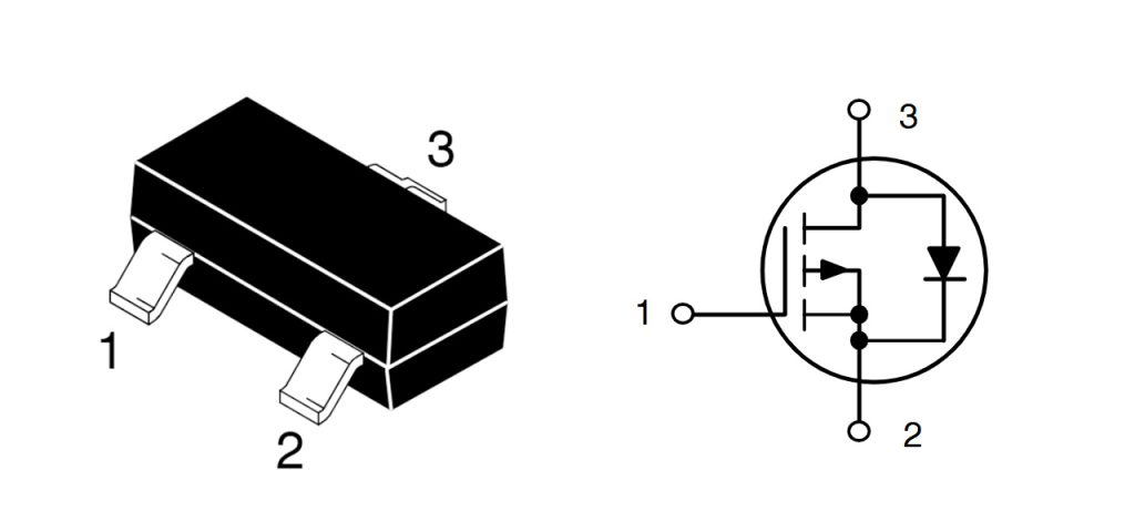
| Pin Number | Pin Name | Description |
|---|---|---|
| 1 | Gate (G) | Gate pin, controls MOSFET switching |
| 2 | Source (S) | Source pin, typically connected to higher potential node (for P-channel MOSFET, connected to positive voltage supply) |
| 3 | Drain (D) | Drain pin, connected to load terminal |
When using the BSS84LT1G MOSFET, keep in mind that the Gate pin is your control point—lowering the gate voltage below the threshold switches it on, while raising it above switches it off. Just be careful not to exceed the maximum rated gate voltage to prevent damaging it.
Since it’s a P-channel MOSFET, your Source pin usually connects to the higher voltage side, like your positive power rail. Double-check this connection to avoid mistakes.
The Drain pin connects directly to your load, with the other side of your load typically going to ground or a lower voltage level.
In your PCB layout, position this MOSFET close to both your load and the control signal. Shorter leads help reduce interference and parasitic inductance. Also, ensure the current and voltage across your MOSFET stay within its ratings to avoid overloading and potential damage.
BSS84LT1G Equivalent P-Channel MOSFET
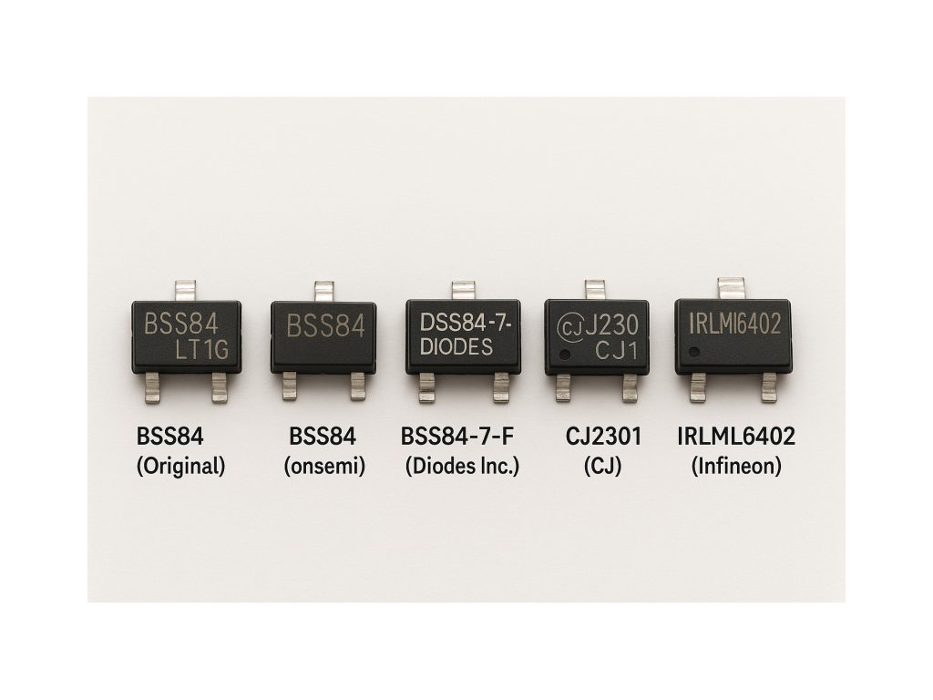
| Parameter/Model | BSS84LT1G (Original) | BSS84 (onsemi) | BSS84-7-F (Diodes Inc.) | CJ2301 (CJ) | IRLML6402 (Infineon) |
|---|---|---|---|---|---|
| Package | SOT-23 | SOT-23 | SOT-23 | SOT-23 | SOT-23 |
| Max Drain-Source Voltage (VDS) | -50 V | -50 V | -50 V | -30 V | -20 V |
| Max Drain Current (ID) | -130 mA | -130 mA | -130 mA | -2.3 A | -3.7 A |
| RDS(on) | 10 Ω @ -5 V | 10 Ω @ -5 V | 10 Ω @ -5 V | 0.1 Ω @ -4.5 V | 0.055 Ω @ -4.5 V |
| Gate-Source Voltage (VGS) Range | ±20 V | ±20 V | ±20 V | ±20 V | ±20 V |
| Power Dissipation (PD) | 225 mW | 225 mW | 225 mW | 350 mW | 1.25 W |
| Logic Level Drive | Yes | Yes | Yes | Yes | Yes |
| Suitable Current Range | Low Current | Low Current | Low Current | Medium Current | Medium Current |
When picking an alternative MOSFET to the BSS84LT1G, first match the basics: voltage and current ratings. For instance, some options like CJ2301 or IRLML6402 might have lower maximum voltages, so double-check if your circuit really needs higher voltage handling.
Next, consider the MOSFET’s on-resistance (R_DS(on)). A lower on-resistance helps your circuit run cooler and more efficiently. If your design cares about efficiency, models like IRLML6402 could be a better fit.
All recommended substitutes come in a compact SOT-23 package, so swapping them onto your PCB is straightforward. They also work well with standard 3.3V or 5V logic signals, making integration easy.
Lastly, watch out for the device’s maximum power dissipation rating. Ensure your chosen replacement won’t overheat in your actual application, keeping things running smoothly and safely.
BSS84LT1G High-Side Switch Circuit
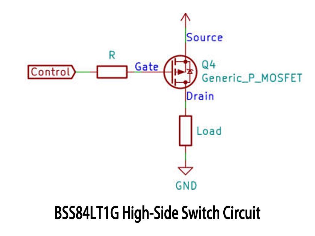
In this high-side switching circuit, the BSS84LT1G MOSFET is your go-to choice. It’s a handy P-channel MOSFET designed specifically to switch power from the positive side of your load.
Here’s a quick rundown:
You connect the source terminal directly to the positive voltage, while the drain connects to your load and then to ground, completing your circuit.
If the gate voltage is almost as high as the source voltage, the MOSFET stays off because there’s basically no voltage difference. But when you lower the gate voltage (usually pulling it down to ground), the gate-to-source voltage (V_GS) becomes negative enough, turning on the MOSFET. Now current flows from source to drain, powering your load.
The BSS84LT1G has a low on-resistance, keeping voltage drop and heat minimal. It’s perfect for battery-powered or low-power circuits where efficiency matters.
BSS84LT1G MOSFET Gate Threshold
The BSS84LT1G MOSFET typically has a gate threshold voltage (V_GS(th)) somewhere between -0.8V and -2.0V.
In plain English, that’s the point where the MOSFET just starts turning on—the voltage difference between gate and source hits this negative threshold. Since it’s a P-channel MOSFET, the gate voltage naturally needs to be negative relative to the source.
Practically speaking, you’ll usually set the gate voltage lower than this threshold—like around -5V—to make sure it’s fully switched on and working efficiently with minimal resistance.
BSS84LT1G Load Switch Application
-
Battery-Operated IoT Sensor Modules
If you’re designing battery-powered IoT gadgets—say a temperature or humidity sensor—you’ll want to squeeze every bit of battery life you can. That’s where the BSS84LT1G MOSFET is handy as a high-side switch. When your sensor isn’t measuring, this MOSFET stays off, keeping the sensor disconnected from the battery. The moment you need data, your microcontroller pulls the gate low, switching the MOSFET on briefly. The sensor powers up just long enough to gather and send data, drastically saving battery power and extending runtime from months to potentially years.
-
Portable Consumer Electronics
Think about smartwatches or fitness bands—small devices with limited battery capacity. Inside, you’ve got sensors like heart-rate monitors, Bluetooth modules, and displays, each needing individual power control. Using a BSS84LT1G MOSFET, you selectively power these modules. For example, when the heart-rate monitor isn’t in use, the MOSFET cuts off its power line to avoid unnecessary current drain. Thanks to its tiny package, low on-resistance, and reliable performance, it’s ideal for these compact gadgets, keeping battery use efficient without wasting space.
BSS84LT1G SMD MOSFET Wiring Example
Wiring Example:
-
Source (S): Connect this directly to your positive voltage source (e.g., +5V battery line).
-
Drain (D): Connect to the positive side of your load (e.g., LED, sensor module). The other side of the load connects to ground.
-
Gate (G): Attach through a resistor (typically 10kΩ–100kΩ) to a GPIO pin of your microcontroller or control circuit.
Practical Scenario:
Suppose you’re powering an LED indicator from a 5V battery source. Connect the BSS84LT1G source pin directly to the battery’s positive terminal. Connect the MOSFET’s drain to the LED’s anode, and then the LED’s cathode to ground through a current-limiting resistor. Use a GPIO pin from your microcontroller to drive the MOSFET gate low (0 V) to turn on the LED. When the GPIO pin is high (near 5 V), the MOSFET turns off, disconnecting the LED from power and saving energy.
This simple wiring approach provides clean and efficient switching for low-voltage, low-current applications, ideal for compact battery-operated devices.
More Like This
~~3.jpg "IRFU9024NPBF")
IRFU9024NPBF
International Rectifier

FDG6335N
onsemi

MMBFJ201
onsemi

IRF3205PBF
International Rectifier

IRFP1405PBF
International Rectifier

IRF3205ZSTRLPBF
International Rectifier

IRFP4229PBF
International Rectifier

IRFB7437PBF
International Rectifier
.jpg "IRLR9343TRPBF")
IRLR9343TRPBF
International Rectifier
IRFP4468PBF
International Rectifier
IRF640NSTRLPBF
International Rectifier

FDS6375
National Semiconductor
Also Add to Cart

IRFR5305PBF
International Rectifier

FDMS7682
Fairchild Semiconductor
.jpg "IRF830PBF")
IRF830PBF
Infineon Technologies

FCD620N60ZF
onsemi

FDMC2523P
Fairchild Semiconductor

FDB52N20TM
Fairchild Semiconductor
FDD5614P
onsemi
IRFB7440PBF
Infineon Technologies
IRF3710PBF
Infineon Technologies

ZXMP6A17GTA
Diodes Incorporated

STY145N65M5
STMicroelectronics

SUD50P10-43L-E3
Vishay Siliconix
Related Products
IRFU9024NPBF
International Rectifier
FDG6335N
onsemi
MMBFJ201
onsemi
IRF3205PBF
International Rectifier
IRFP1405PBF
International Rectifier
IRF3205ZSTRLPBF
International Rectifier
IRFP4229PBF
International Rectifier
IRFB7437PBF
International Rectifier
IRLR9343TRPBF
International Rectifier
IRFP4468PBF
International Rectifier
IRF640NSTRLPBF
International Rectifier
FDS6375
National Semiconductor
IRFB4332PBF
International Rectifier

IRFP3306PBF
International Rectifier

NVTFS5811NLTAG
onsemi
NVTFS4823NTWG
onsemi

NVD5117PLT4G
onsemi
IRF200S234
Infineon Technologies
IRF840PBF
Infineon Technologies

AO4407
Alpha & Omega Semiconductor Inc.

2SK3377-Z-E1-AZ
Renesas Electronics America Inc

NVD5867NLT4G
onsemi

NVMFS5A160PLZWFT1G
onsemi

FDWS9510L-F085
onsemi
FDWS9509L-F085
onsemi
NVTFS5826NLWFTAG
onsemi

AON7401L
Alpha & Omega Semiconductor Inc.
AO4407AL
Alpha & Omega Semiconductor Inc.

AO3407
Alpha & Omega Semiconductor Inc.

CPH3461-TL-W
onsemi
Please send RFQ , we will respond immediately.
