
ENC28J60 Arduino Nano Ethernet Shield | Datasheet
- Contact Gender: -
- Material: -
- Maximum Bundle Diameter: -
- Package: -


FREE delivery for orders over HK$250.00

Quick response, quick quotaton

Flash shipment,no worries after sales

Original channel,guarantee of the authentic products
ENC28J60-I/SS Supplier and MICROCHIP ENC28J60T-I/SS Distributor in China – Rantle East Electronic
Enc28j60
The ENC28J60 by Microchip is a versatile Ethernet controller, ideal for embedded systems, especially if you need to connect your project to a local area network (LAN). It uses an SPI interface, making it easy to communicate with microcontrollers like Arduino. The chip operates at 3.3V and supports networking protocols like TCP/IP, ARP, UDP, and ICMP, which you can implement using external software or libraries provided by Microchip. With a 10Mbps Ethernet connection, it also includes 8KB of internal memory for handling network data. The ENC28J60 is designed for low power consumption, making it perfect for IoT devices, embedded systems without built-in network interfaces, and industrial applications. It offers advanced features like automatic packet filtering and hardware queue management to reduce CPU load. Whether you’re building smart home devices or industrial controllers, the ENC28J60 is a reliable solution for easy Ethernet connectivity.
Enc28j60 Pinout
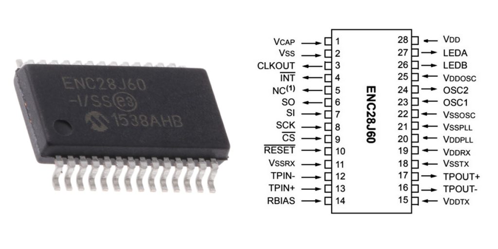
| Pin | Pin Name | Description |
|---|---|---|
| 1 | VCAP | Capacitor connection for internal voltage regulator |
| 2 | VSS | Ground (GND) |
| 3 | CLKOUT | Clock output for external clock synchronization |
| 4 | INT | Interrupt pin (active low) |
| 5 | NC (1) | No connection |
| 6 | SO | SPI output pin (Serial Data Output) |
| 7 | SI | SPI input pin (Serial Data Input) |
| 8 | SCK | SPI clock pin (Serial Clock Input) |
| 9 | CS | Chip Select (active low) |
| 10 | RESET | Reset pin (active low) |
| 11 | VSSRDX | Ground for receive section |
| 12 | TPIN+ | Transmit Positive Voltage |
| 13 | RBIAS | Bias resistor for internal circuitry |
| 14 | VDDTX | Supply voltage for transmit section |
| 15 | VDDRDX | Supply voltage for receive section |
| 16 | TPOUT+ | Transmit output pin (Differential) |
| 17 | VSSSTX | Ground for transmit section |
| 18 | VDPLL | Power supply for PLL |
| 19 | VSSOSOS | Ground for oscillator section |
| 20 | OSC1 | Oscillator input pin |
| 21 | OSC2 | Oscillator output pin |
| 22 | VDDOSC | Power supply for oscillator |
| 23 | LEDA | LED A indicator |
| 24 | LEDB | LED B indicator |
| 25 | VDD | Power supply for the chip |
| 26 | LEDD | LED D indicator |
| 27 | VDDRDX | Power supply for receive section |
| 28 | VSS | Ground (GND) |
When connecting the ENC28J60 Ethernet controller, here’s how the pins work. First, you’ll need to power the chip through the VDD and VSS pins—VSS goes to GND, and VDD usually gets 3.3V for proper operation. For communication, use the SPI pins: SO (Serial Output) sends data to the microcontroller, SI (Serial Input) receives data, SCK provides the clock signal, and CS is used to select the chip for communication. If you need to trigger interrupts, the INT pin goes low when something happens. There are also LED pins (LEDA and LEDB) to show the chip’s status, and OSC1 and OSC2 connect to an external crystal for clock signals. Don’t forget the RESET pin to reset the chip, and ensure power for the receive and transmit sections with VDDRX and VDDTX. For stable operation, add decoupling capacitors near the power pins. Always double-check your wiring and ensure the power supply is correct!
Enc28j60 Equivalent Ethernet Controller
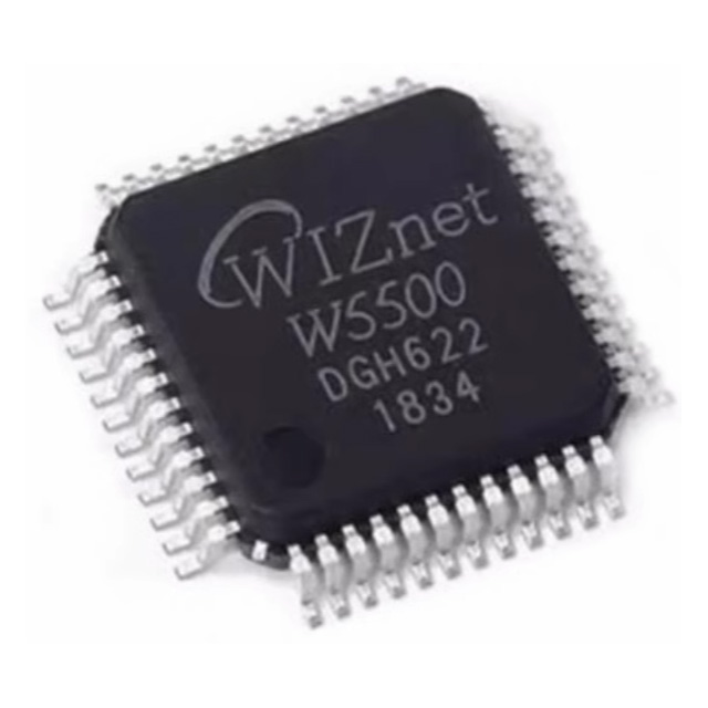
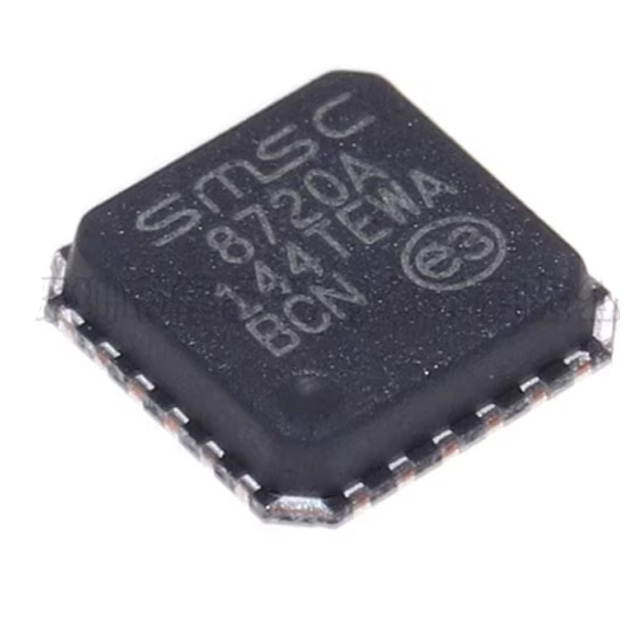
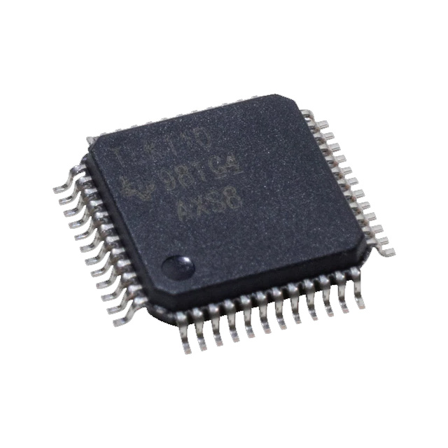
| Parameters | ENC28J60 | W5500 | LAN8720A | TLK110 | DP83848C |
|---|---|---|---|---|---|
| Package Type | SOIC-28 | LQFP-32 | LQFP-24 | QFN-32 | LQFP-48 |
| Operating Voltage Range | 3.3V ±10% | 3.3V | 3.3V | 3.3V ±10% | 3.3V ±10% |
| Max Data Rate | 10 Mbps | 100 Mbps | 100 Mbps | 100 Mbps | 100 Mbps |
| Interface Type | SPI | SPI | RMII | MII/RMII | MII/RMII |
| Features | Low power, supports SPI interface, supports TCP/IP protocol stack | Low power, supports 100Mbps ethernet connection | Efficient protocol support, suitable for industrial applications | High performance, suitable for high-speed communication, supports PHY interface | High performance, supports high-speed communication, supports PHY interface |
When choosing an Ethernet controller, you’ll want to consider your project’s needs. The ENC28J60 is a great choice for low-speed network applications, offering a 10 Mbps communication rate and 3.3V power. However, if you need faster speeds, the W5500 or LAN8720A might be better. The W5500 supports 100 Mbps and comes with a built-in TCP/IP stack, making it easier for development. On the other hand, the LAN8720A also offers 100 Mbps and is especially suitable for low-power embedded systems, particularly if you’re using RMII interfaces. For industrial applications or long-distance communication, the TLK110 and DP83848C offer even more reliable performance and support MII/RMII interfaces. So, depending on your speed requirements and interface needs, you can pick the best alternative: W5500 or LAN8720A for higher speeds, or TLK110 and DP83848C for industrial-grade performance.
Enc28j60 Ethernet Circuit Example
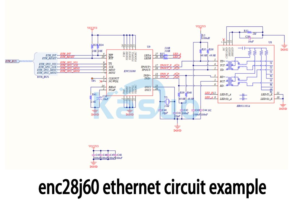
In this circuit, the ENC28J60 Ethernet controller communicates with the MCU via SPI. You’ll find that the ETH_SPI_SCK, ETH_SPI_MISO, ETH_SPI_MOSI, and ETH_SPI_NSS pins handle the SPI data transfer. The INT, RESET, and OSC pins are used for interrupt handling, reset control, and clock synchronization. The controller also connects to LEDs (LED_A and LED_B) to indicate the Ethernet connection status.
The HR911105A PHY chip is responsible for sending and receiving Ethernet signals. It uses differential signal pairs like TD+ and TD- for transmission, and RD+ and RD- for receiving. The circuit uses capacitors (C39, C42, C43) to filter and stabilize the power, minimizing noise interference, and resistors (R33 to R40) ensure signal integrity.
This design ensures reliable Ethernet communication, with proper power filtering and signal integrity, making it ideal for stable performance even in noisy environments.
Enc28j60 Spi Communication Setup
To get the ENC28J60 Ethernet controller up and running, you’ll first need to connect it to your MCU via SPI. Connect the SCK, MISO, MOSI, and NSS pins for communication. The SPI clock settings should be set to Mode 0, with the correct frequency between 1MHz and 20MHz, depending on your MCU’s capabilities.
In your software, you’ll initialize the SPI interface in Mode 0 and set the clock speed. The chip select (NSS) pin controls when the ENC28J60 is active—make sure it’s pulled low before starting communication and high when done.
Once connected, you can write and read data to/from the ENC28J60 using SPI commands. This allows you to configure the device’s registers, like setting its MAC and IP addresses.
When you’re debugging, check the communication signals with an oscilloscope or logic analyzer to ensure proper data transmission, and make sure the chip select pin is properly controlled for each transaction.
Enc28j60 Esp8266 Wiring
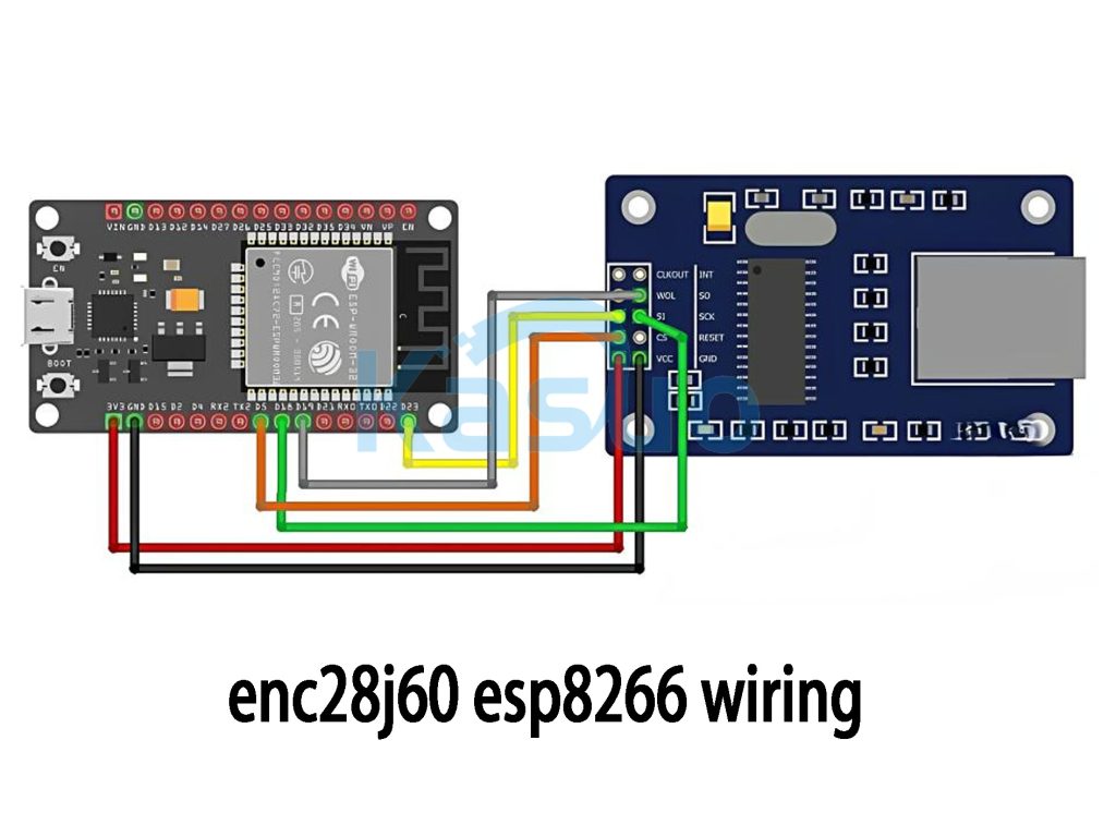
To connect the ESP8266 to the ENC28J60, start by wiring the power. Connect the 3.3V pin of the ESP8266 to the VCC pin of the ENC28J60, and the ground (GND) pins of both devices together.
For SPI communication, connect the SCK pin (clock) of the ESP8266 to the SCK pin on the ENC28J60, and the MISO and MOSI pins for data transfer. You’ll also need to link the NSS (chip select) pin on the ESP8266 to the ENC28J60 to control when the SPI communication is active.
Make sure the power supply is stable at 3.3V—using 5V could damage both devices. Additionally, check if the SPI pins are available on the ESP8266, as other functions may use them.
Lastly, to get the communication working, ensure you have the right libraries like UIPEthernet or EthernetENC installed in your development environment.
Enc28j60 3.3v Power Supply
When powering the ENC28J60, it’s important to provide a stable 3.3V supply with enough current for the chip to function properly. This chip typically requires between 50mA to 100mA, with brief current spikes during data transmission.
You can use a Low Dropout Regulator (LDO) like the AMS1117-3.3 if you’re stepping down from 5V to 3.3V. However, if you’re dealing with higher currents or need more efficiency, a DC-DC Buck Converter like the LM2596 works better, especially if you’re starting with 12V or 5V input.
Don’t forget to add filtering capacitors (around 10µF each) at the input and output of your regulator to keep the power clean and stable.
Always ensure your voltage is 3.3V—using 5V could damage the ENC28J60. With the right setup, your ENC28J60 should perform reliably without issues.
Enc28j60 Ethernet Module Schematic
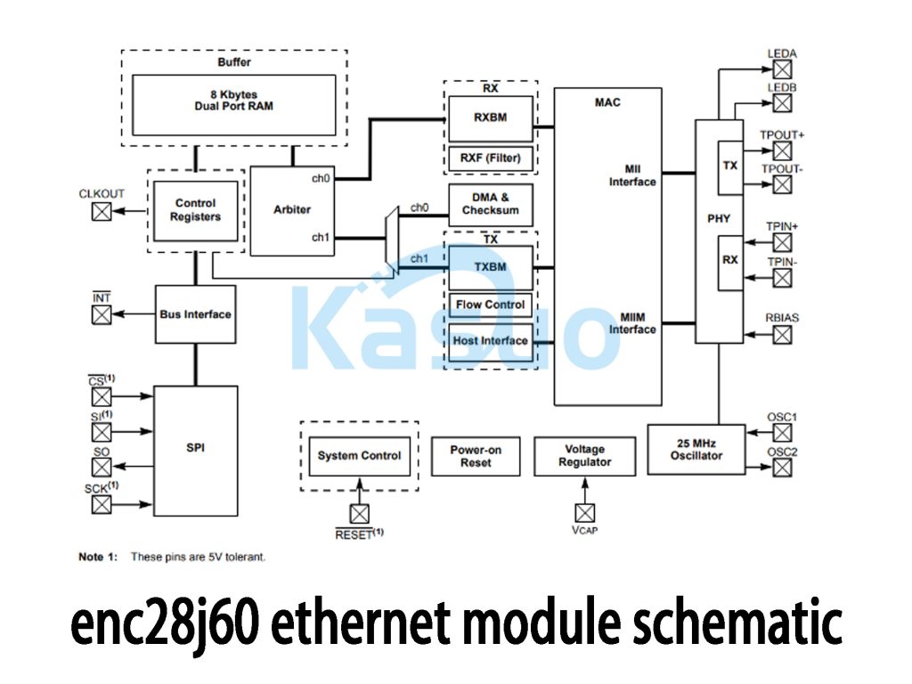
Let’s break down the ENC28J60’s key features for a better understanding:
-
System Overview: The ENC28J60 has an 8KB dual-port RAM to store packets, allowing smooth data flow during both receive and send operations. It also has control registers that manage settings and status, along with an arbiter to handle bus access and prevent conflicts.
-
Data Transfer: It handles data reception (RX) with RX buffers and filtering, and manages data transmission (TX) with buffers and flow control. DMA and checksum features improve efficiency and ensure data integrity.
-
Interfaces: It uses a MAC module to handle Ethernet communication and an MII interface for higher-level protocol support. The PHY layer takes care of electrical signal transmission to the network.
-
Power & Clock: It uses a 25 MHz oscillator for timing, a voltage regulator for stable power, and includes a reset pin for initialization.
-
Connectivity: SPI interface makes communication easy with the MCU, and LEDs show network and data transmission status.
This chip is designed for stable and efficient network communication, ideal for various embedded systems.
More Like This
Also Add to Cart

MT53E256M32D2DS-046 IT:B
Micron

MQM9700-NS2R
NVIDIA

USB83340AM-B-V02
Microchip Technology
ADT7301ARTZ
Analog Devices
TPS7A4901DGN
Texas Instruments
74AVCH2T45DC
Nexperia

USL00-30L-A
JLCPCB Assembly

MT48LC8M16A2P-75 IT:G
Micron
HOA6567-001
Honeywell
ADN8835ACPZ
Analog Devices
BZX384-B12
Nexperia
ADG1413YCPZ
Analog Devices
Related Products
AD8552
Analog Devices
AD8601
Analog Devices
AD8539
Analog Devices
AD8605
Analog Devices
AD8551
Analog Devices
AD8606
Analog Devices
AD8608
Analog Devices
AD8604
Analog Devices
AD8602
Analog Devices
AD8655
Analog Devices
AD8538
Analog Devices
AD8554
Analog Devices
FP40R12KT3
Infineon Technologies

FP75R12KT3
Infineon Technologies
FP25R12KT3
Infineon Technologies
FP35R12KT4
Infineon Technologies

FP15R12W1T4
Infineon Technologies
FS100R12KT4
Infineon Technologies

FP150R12KT4
Infineon Technologies
FP50R12KT3
Infineon Technologies

FP25R12KT4
Infineon Technologies
FP35R12W2T4
Infineon Technologies
FP25R12W2T4
Infineon Technologies

FP10R12W1T4
Infineon Technologies

ADUM1201ARZ
Analog Devices
AD5314ACPZ
Analog Devices
OP27G
Analog Devices
AD5314BCPZ
Analog Devices
AD8054
Analog Devices
AD5324BCPZ
Analog Devices
Please send RFQ , we will respond immediately.
