
FDN340P | Datasheet, Arduino, Equivalent, Application Note Fairchild Semiconductor
- FET Type: P-Channel
- Drainto Source Voltage(Vdss): 20 V
- Current-Continuous Drain(Id)@25°C: 2A (Ta)
- Package: Die


FREE delivery for orders over HK$250.00

Quick response, quick quotaton

Flash shipment,no worries after sales

Original channel,guarantee of the authentic products
FDN340P
The FDN340P is a low-power N-channel MOSFET perfect for tasks like power management and switching. It can handle up to 30V and 4.8A, making it suitable for low-voltage applications. The gate threshold voltage is between 1V and 3V, so it’s great for logic-level control, meaning you can drive it directly with low-voltage microcontrollers. With an Rds(on) of 0.075Ω, it’s efficient with minimal power loss. Its small SOT-23 package is ideal for space-tight designs, and it’s fast enough for applications like PWM circuits or motor control. This MOSFET is commonly used in low-voltage systems, DC-DC converters, and motor drivers.
FDN340P Pinout
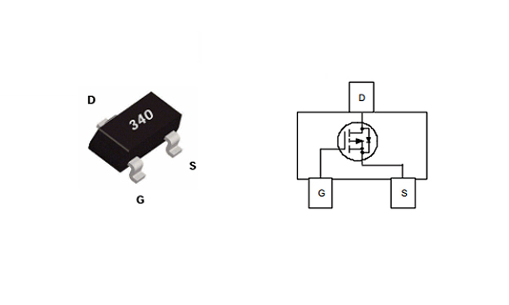
| Pin Number | Pin Name | Function |
|---|---|---|
| 1 | Gate (G) | Controls the MOSFET, used to turn it on/off by applying a voltage relative to the source pin. |
| 2 | Drain (D) | The current flows from the drain to the source when the MOSFET is on. |
| 3 | Source (S) | The reference point for the gate voltage, and the current flows from the drain to the source. |
The gate (G) controls the MOSFET’s switching. To turn it on, apply a voltage (usually between 3V-5V) between the gate and the source. The higher the voltage, the lower the MOSFET’s Rds(on), allowing more current to flow. To turn it off, pull the gate voltage to ground or close to the source voltage. The drain (D) is where you connect your load, and current flows from the drain to the source when the MOSFET is on. The source (S) is the reference for the gate and where current exits the MOSFET. In most cases, it’s connected to ground or the negative side of the load.
FDN340P Equivalent

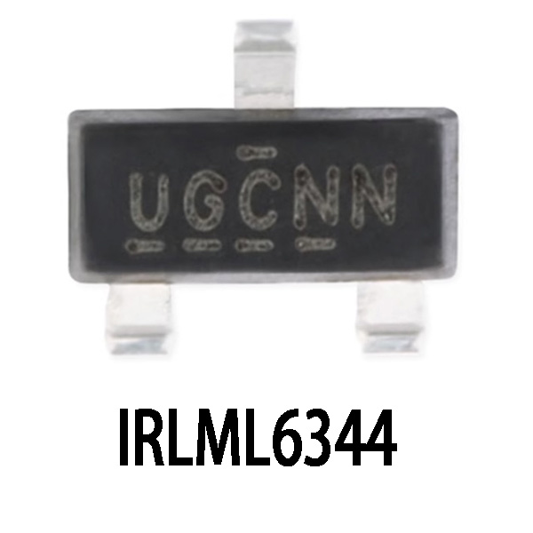
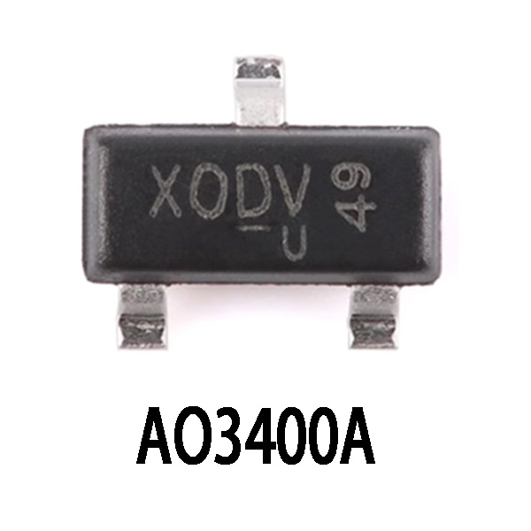
| Parameter | FDN340P | IRLML6344 | AO3400A |
|---|---|---|---|
| Vds (Drain-Source Voltage) | 30V | 30V | 30V |
| Id (Continuous Drain Current) | 4.8A | 5A | 5.8A |
| Rds(on) (Drain-Source On Resistance) | 0.075Ω | 0.085Ω | 0.055Ω |
| Gate Threshold Voltage (Vgs(th)) | 1V – 3V | 1V – 3V | 1V – 3V |
| Package Type | SOT-23 | SOT-23 | SOT-23</td |
| Gate Charge (Qg) | 6.5nC | 5nC | 6nC |
| Application | Low-voltage power switching, logic-level control | Low-voltage power switching, logic-level control | Low-voltage switching, motor drivers |
If you’re looking for alternatives to the FDN340P, here are some good options. The IRLML6344 has a slightly higher current rating (5A) but similar Rds(on) (0.085Ω), making it a solid choice for low-power switching. The AO3400A has an even lower Rds(on) of 0.055Ω, which makes it more efficient for higher current applications (5.8A). All these alternatives have similar gate threshold voltages (1V-3V), so they’ll work well with low-voltage logic control.
FDN340P Load Switch Circuit Example

In the FDN340P load switch circuit, the MOSFET controls the flow of current to the load. When you apply a voltage (Vgs) to the gate, it turns the MOSFET on, allowing current to flow from the drain to the source, powering the load. The gate resistor (Rgen) helps regulate the gate current and ensures proper switching. When Vgs is high enough (above the threshold), the MOSFET turns on and lets current flow through the load. When Vgs is low, the MOSFET turns off, cutting power to the load.
The FDN340P is great for low-voltage power management, as its low Rds(on) reduces power loss. Ensure the gate voltage is enough to fully turn the MOSFET on, typically using a 3.3V or 5V signal. This circuit is perfect for applications like battery-powered systems or efficient load control.
FDN340P Reverse Polarity Protection
To protect your circuit from reverse polarity using the FDN340P MOSFET, you can take advantage of its ability to block current in one direction. When the power supply is connected with the correct polarity (positive to drain and negative to source), the MOSFET turns on, letting current flow through the load. If the polarity is reversed, the MOSFET remains off, preventing current from flowing and protecting your circuit. The FDN340P is efficient because it doesn’t have the typical voltage drop that diodes do. With its low Rds(on), it minimizes power loss in normal operation, making it a great choice for reverse polarity protection.
FDN340P Gate Resistor Calculation
When calculating the gate resistor for the FDN340P MOSFET, you’re trying to control how fast the MOSFET switches, while limiting the current flowing into the gate. To start, the FDN340P has a gate charge (Qg) of around 6.5 nC at 5V. You’ll also need to know the switching frequency—say, 100 kHz. Using this, you can calculate the gate current (Ig) by multiplying Qg and the frequency. For 100 kHz, it’s 0.65 mA.
Now, you can use Ohm’s law to find the gate resistor (Rgen). With a gate voltage (Vgs) of 5V and Ig at 0.65 mA, Rgen will be around 7.7kΩ. For practical purposes, values between 10Ω to 100Ω work well for fast switching, while 1kΩ to 10kΩ is better for slower switching with less noise.
More Like This
~~3.jpg "IRFU9024NPBF")
IRFU9024NPBF
International Rectifier

FDG6335N
onsemi

MMBFJ201
onsemi

IRF3205PBF
International Rectifier

IRFP1405PBF
International Rectifier

IRF3205ZSTRLPBF
International Rectifier

IRFP4229PBF
International Rectifier

IRFB7437PBF
International Rectifier
.jpg "IRLR9343TRPBF")
IRLR9343TRPBF
International Rectifier
IRFP4468PBF
International Rectifier
IRF640NSTRLPBF
International Rectifier

FDS6375
National Semiconductor
Also Add to Cart

IRFR3607TRPBF
Infineon Technologies

FDT3612
Fairchild Semiconductor

STB6NK90ZT4
STMicroelectronics

IRFR5505
Infineon Technologies
;;2.jpg "STD18N55M5")
STD18N55M5
STMicroelectronics

CSD17571Q2
Texas Instruments

CSD17483F4
Texas Instruments

NVMFS5C426NAFT1G
onsemi
IRLR3110ZTRPBF
Infineon Technologies

STF13N60M2
STMicroelectronics

IRF250P224
Infineon Technologies

STH13N120K5-2AG
STMicroelectronics
Related Products
IRFU9024NPBF
International Rectifier
FDG6335N
onsemi
MMBFJ201
onsemi
IRF3205PBF
International Rectifier
IRFP1405PBF
International Rectifier
IRF3205ZSTRLPBF
International Rectifier
IRFP4229PBF
International Rectifier
IRFB7437PBF
International Rectifier
IRLR9343TRPBF
International Rectifier
IRFP4468PBF
International Rectifier
IRF640NSTRLPBF
International Rectifier
FDS6375
National Semiconductor
IRFB4332PBF
International Rectifier

IRFP3306PBF
International Rectifier

NVTFS5811NLTAG
onsemi
NVTFS4823NTWG
onsemi

NVD5117PLT4G
onsemi
IRF200S234
Infineon Technologies
.jpg "IRF840PBF")
IRF840PBF
Infineon Technologies

AO4407
Alpha & Omega Semiconductor Inc.

2SK3377-Z-E1-AZ
Renesas Electronics America Inc

NVD5867NLT4G
onsemi
NVMFS5A160PLZWFT1G
onsemi

FDWS9510L-F085
onsemi
FDWS9509L-F085
onsemi
NVTFS5826NLWFTAG
onsemi

AON7401L
Alpha & Omega Semiconductor Inc.
AO4407AL
Alpha & Omega Semiconductor Inc.

AO3407
Alpha & Omega Semiconductor Inc.

CPH3461-TL-W
onsemi
Please send RFQ , we will respond immediately.
