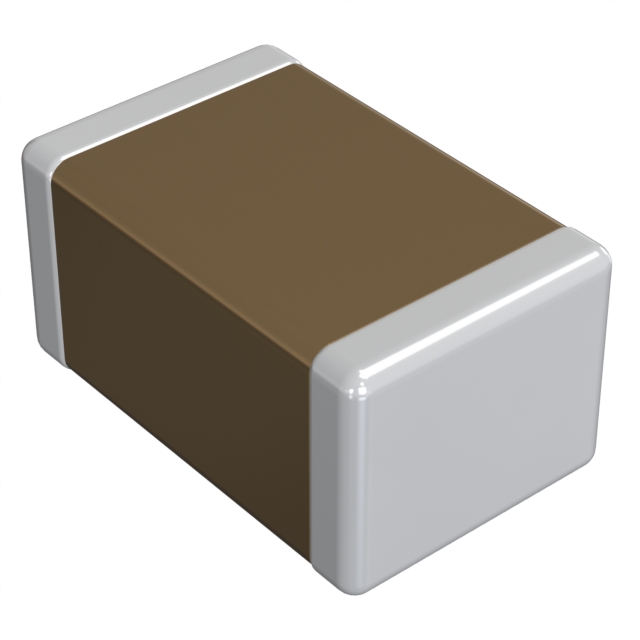
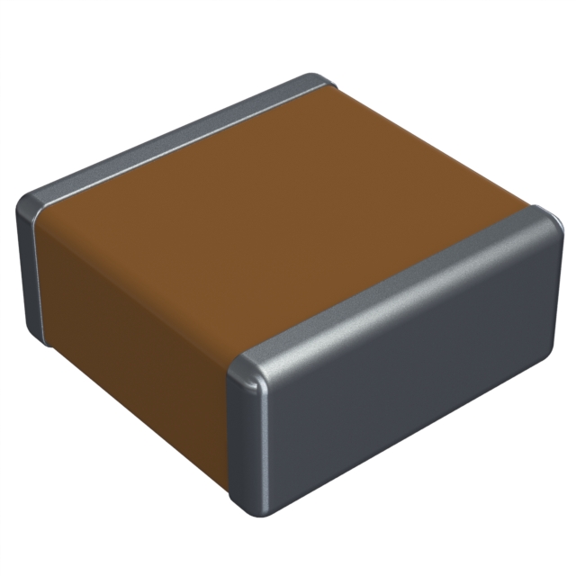
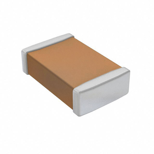
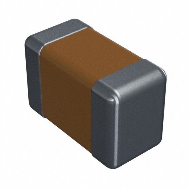
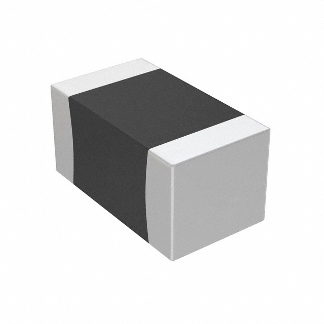
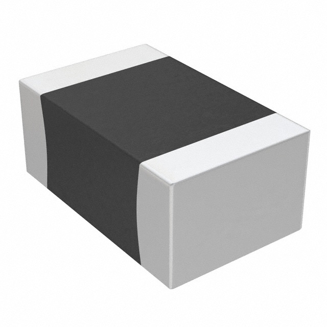
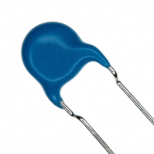
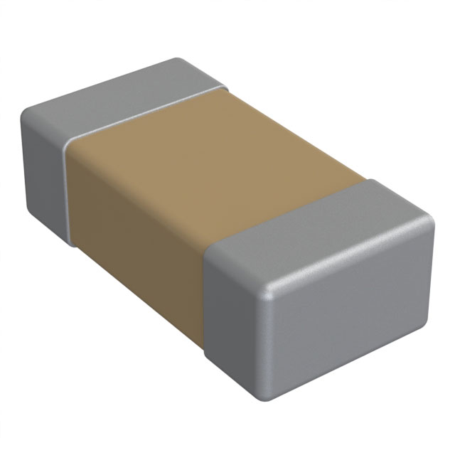
GRM188R72A104KA35D Capacitor 0.1µF 100V 0603
- Capacitance: 0.1 µF
- Voltage - Rated: 100V
- Tolerance: ±10%
- Package: 0603 (1608 Metric)

FREE delivery for orders over HK$250.00

Quick response, quick quotaton

Flash shipment,no worries after sales

Original channel,guarantee of the authentic products
GRM188R72A104KA35D
The GRM188R72A104KA35D is a 2.2 µF ceramic capacitor that’s great for decoupling, filtering, and smoothing applications. It can handle up to 25V, which is important to ensure it won’t break down under high voltage. It’s a multilayer ceramic capacitor (MLCC), which means it’s compact, affordable, and performs reliably in different conditions.
With a tolerance of ±20%, the actual capacitance could vary by up to 20% from the stated value. The X7R dielectric helps the capacitor stay stable across a wide temperature range from -55°C to 125°C, making it versatile in many environments. The 0805 package size is small, perfect for compact designs in things like mobile devices and computers.
GRM188R72A104KA35D Capacitor Footprint
For the GRM188R72A104KA35D in the 0805 package, here’s what you need to know:
-
Length: 2.0 mm (0.079 inches)
-
Width: 1.25 mm (0.049 inches)
-
Height: Around 0.8 mm (0.031 inches), though it can vary slightly.
For the pads, you’ll need:
-
Pad Length: 1.35 mm
-
Pad Width: 0.85 mm
-
Spacing Between Pads: 1.25 mm (this might vary a bit depending on how you assemble it).
When setting up your layout, make sure the pads are aligned and have smooth edges to make soldering easier and avoid short circuits. Following IPC-7351 standards or any recommendations from the manufacturer will ensure the best results.
GRM188R72A104KA35D Equivalent


| Parameter | GRM188R72A104KA35D | C1608X7R1E105K | CL21B105KQNNC |
|---|---|---|---|
| Capacitance | 0.1 µF | 0.1 µF | 0.1 µF |
| Voltage Rating | 25V | 25V | 25V |
| Dielectric Material | X7R | X7R | X7R |
| Tolerance | ±10% | ±10% | ±10% |
| Package Size | 0805 | 0805 | 0805 |
| Temperature Range | -55°C to +125°C | -55°C to +125°C | -55°C to +125°C |
| ESR (Equivalent Series Resistance) | Low | Low | Low |
| Applications | General-purpose, decoupling, filtering | General-purpose, decoupling, filtering | General-purpose, decoupling, filtering |
These three capacitors are pretty similar. They all have 0.1 µF capacitance and a 25V voltage rating, so they’ll work for the same applications.
They all use an X7R dielectric, which is stable across a wide temperature range of -55°C to +125°C. This means they’re reliable for decoupling, filtering, and smoothing in many circuits.
The tolerance is ±10% for all three, which is typical for general-purpose capacitors of this size.
If you’re considering alternatives, the Samsung CL21B105KQNNNC and TDK C1608X7R1E105K are solid options. They both match in terms of capacitance, voltage, and size. The main differences will be slight manufacturer-specific tolerances or performance variations, but they’ll still perform the same for most applications.
GRM188R72A104KA35D Bypass Capacitor Circuit

The GRM188R72A104KA35D bypass capacitor plays a key role in stabilizing power supply voltage and filtering out high-frequency noise in circuits. In this setup, capacitors like C1, C2, and CW1, CW2 are used to smooth the voltage by removing unwanted high-frequency signals. You’ll often see aluminum capacitors for bulk capacitance (C1) and ceramic capacitors for high-frequency filtering (C2).
The inductor (L1) helps to further smooth the power by opposing high-frequency currents, which is typical in DC-DC converters or other sensitive power circuits. The resistors (like RW1 and RW2) limit current flow and help reduce unwanted signals.
The switch (SW2) allows you to test the power supply’s performance under different loads, and the 10 MHz square wave (V2) helps assess how well the capacitors filter high-frequency noise.
In short, this circuit tests how well bypass capacitors handle noise and maintain stable voltage for sensitive components.
GRM188R72A104KA35D PCB Decoupling Guide
When using the GRM188R72A104KA35D ceramic capacitor in your PCB decoupling circuit, here’s what you should keep in mind:
Place the 100nF capacitor as close as possible to the power pins of your ICs or sensitive components. This reduces the path for noise and minimizes inductance, ensuring effective filtering of high-frequency noise.
For better performance, pair it with larger capacitors like 10 µF or 100 µF. The smaller capacitor handles high-frequency noise, while the larger one smooths out lower-frequency fluctuations.
Keep the traces between the capacitor and the component’s power pins as short and wide as possible. This reduces parasitic inductance and resistance, improving the decoupling.
Lastly, make sure the ground connection is solid and has low impedance, ideally with a direct path to the ground plane, to maintain stability.
GRM188R72A104KA35D Capacitor Layout Tips
When you’re setting up the GRM188R72A104KA35D (100nF) ceramic capacitor on your PCB, there are a few things to keep in mind for the best performance:
Place the capacitor as close as possible to the power pins of the IC or sensitive components to reduce trace inductance and improve noise filtering. Make sure the traces between the capacitor and power/ground pins are short and wide—this reduces impedance and boosts efficiency.
Using a solid ground plane beneath the capacitor helps reduce return path impedance, making it more effective for high-frequency filtering. Even though the GRM188R72A104KA35D is non-polarized, it’s good practice to align the leads with the current flow to minimize unnecessary inductance.
For high-speed circuits, consider combining capacitors with different values (like 100nF and larger ones) to handle a broader range of frequencies and improve noise suppression.
