
IRF510 pinout & amplifier circuit | audio amplifier
- Supplier Device Package: TO-220AB
- FET Type: N-Channel
- Drain to Source Voltage (Vdss): 100 V
- Package: TO-220-3


FREE delivery for orders over HK$250.00

Quick response, quick quotaton

Flash shipment,no worries after sales

Original channel,guarantee of the authentic products
IRF510 MOSFET
IRF510
The IRF510 is a popular N-channel enhancement-mode MOSFET that’s ideal for medium-power switching and amplifier circuits. It features a low on-resistance of about 0.54Ω, handles voltages up to 100V, and currents around 5.6A. If you’re using it with an Arduino or other microcontrollers, its typical gate threshold voltage of around 4V makes it great for driving loads or as a simple switch. It’s also excellent for RF amplifier designs, especially in HF/VHF ranges. You’ll usually see it in the TO-220 package, easy to mount but keep an eye on heat management.
IRF510 Pinout
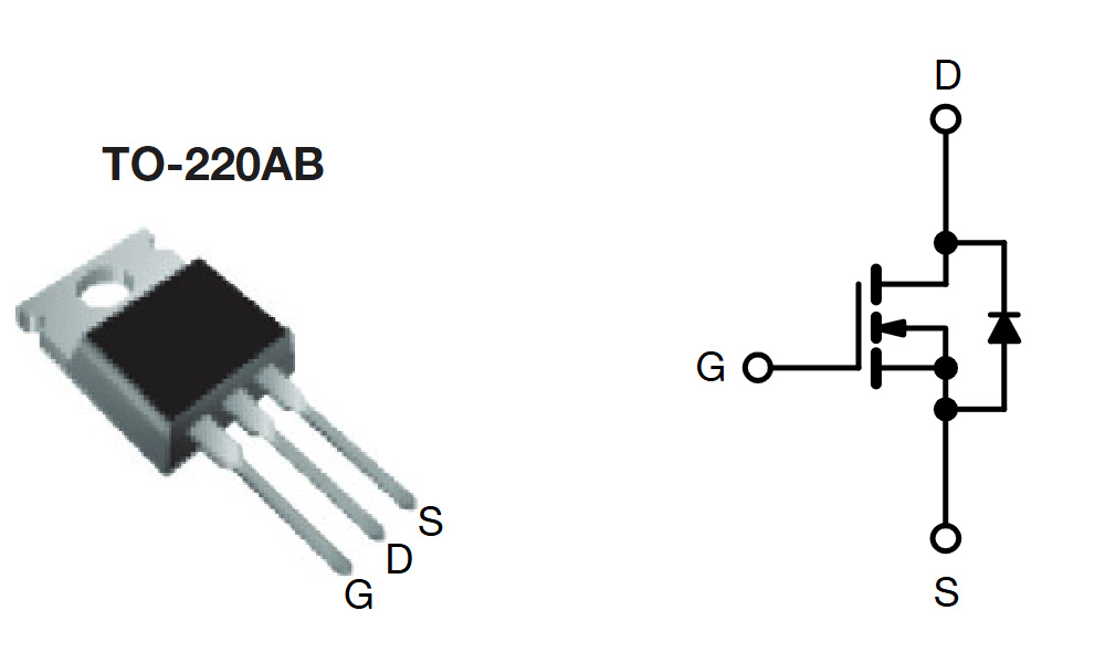
| Pin Number | Pin Name | Function Description |
|---|---|---|
| 1 | Gate (G) | Controls the MOSFET switching on and off |
| 2 | Drain (D) | Connected to the load |
| 3 | Source (S) | Usually connected to ground |
When wiring up an IRF510, the gate (G) connects directly to your control signal, which switches the MOSFET on or off. The drain (D) is usually hooked to your load or the high-voltage side, while the source (S) typically goes straight to ground. One thing to watch out for is static electricity—MOSFET gates are pretty sensitive, so discharging yourself before handling helps. Also, if you’re running it at higher power, attaching a heatsink is a smart move to keep things running cool and stable.
IRF510 Equivalent


| Parameter / Model | IRF510 | IRF520 | IRF530 | IRF540 |
|---|---|---|---|---|
| Polarity Type | N-Channel | N-Channel | N-Channel | N-Channel |
| Drain-Source Voltage (VDSS) | 100 V | 100 V | 100 V | 100 V |
| Continuous Drain Current (ID) | 5.6 A | 9.7 A | 14 A | 33 A |
| On-Resistance (RDS(on)) | 0.54 Ω | 0.27 Ω | 0.16 Ω | 0.077 Ω |
| Power Dissipation (PD) | 43 W | 48 W | 88 W | 150 W |
| Gate-Source Voltage (VGS) | ±20 V | ±20 V | ±20 V | ±20 V |
| Package Type | TO-220 | TO-220 | TO-220 | TO-220 |
The IRF510, IRF520, IRF530, and IRF540 share identical pin layouts and polarities, making them interchangeable. The difference is, IRF520, IRF530, and IRF540 can handle higher currents and have lower on-resistance. So, if you’re driving motors or heavier loads, choosing IRF530 or IRF540 will give you better efficiency and less heat. But for basic low-power switching circuits, sticking with the IRF510 is just fine—no need for an unnecessary upgrade.
IRF510 Amplifier Circuit Example
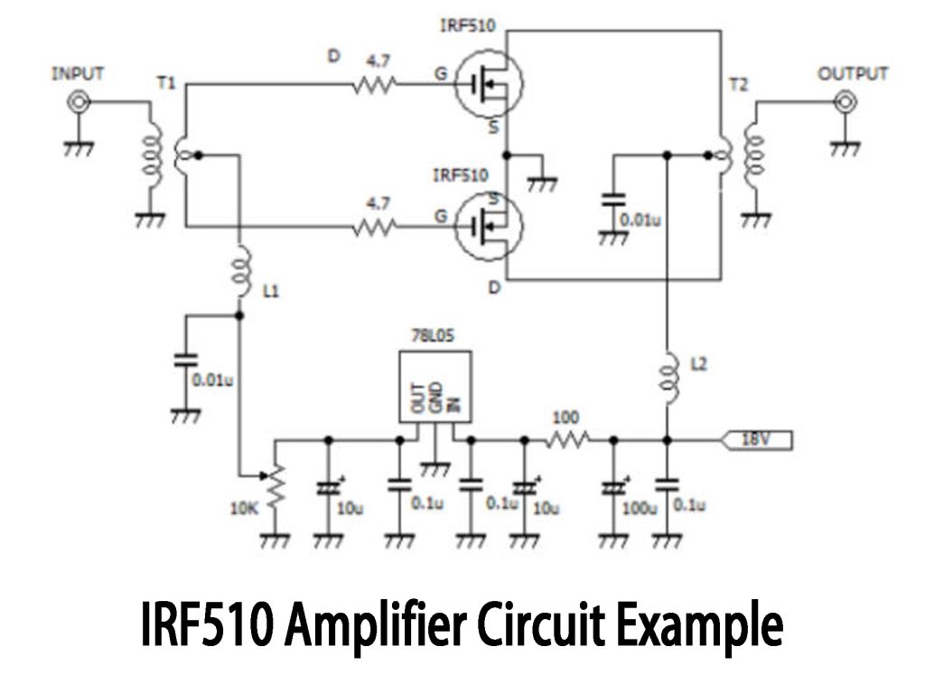
This push-pull amplifier circuit uses two IRF510 MOSFETs to amplify RF signals effectively. It works by first splitting your input RF signal through transformer T1 into two opposite phases. These signals then drive each MOSFET alternately, combining again at transformer T2 to produce the amplified RF output. Both MOSFET sources go to ground, while drains connect through T2 and choke L2 to your 18V DC supply, keeping RF interference out of your power line. A 78L05 regulator supplies a steady 5V gate bias for stable operation. Remember, heatsinks are important here, and don’t skip the 4.7Ω gate resistor—it prevents unwanted high-frequency oscillations. Also, choosing the right transformers and inductors based on your operating frequency makes a big difference.
IRF510 Gate Drive Circuit
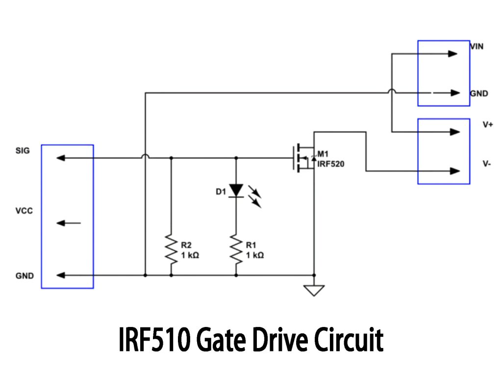
This simple circuit uses an IRF510 MOSFET as a basic low-side switch. Your input signal (SIG) drives the gate through two 1kΩ resistors (R1 and R2), ensuring the MOSFET turns on smoothly. When the MOSFET gate is driven, the LED (D1) lights up, indicating your load is activated. This setup works best for low-frequency or slower switching applications. If you’re handling higher current loads, remember the IRF510 has a slightly higher on-resistance and limited current handling, meaning better heat dissipation is needed. For higher frequencies or precise PWM control, a dedicated MOSFET driver chip would be beneficial.
IRF510 Application
The IRF510 MOSFET is commonly used, especially in RF amplifiers and basic switching power circuits. For example, if you’re into amateur radio and want to build your own shortwave transmitter, IRF510 works great for push-pull or single-ended RF amplifiers. It’s also handy for simple DC-DC converters, like stepping down from 12V to 5V to power a microcontroller. In short, it’s ideal for radio frequency amplification and small-scale power regulation projects.
IRF510 Switching Power Supply Use
The IRF510 MOSFET is super handy when you’re building small-scale switching power supplies—like basic buck, boost, or flyback circuits. For instance, if you need to step 12V down to 5V to power a microcontroller, pairing it with a PWM controller makes it easy. Or, for educational or experimental setups, a simple isolated flyback power supply using IRF510 and a small transformer works well. Just remember, it’s good for power levels under about 40 watts; anything higher might overheat, so you’ll need a tougher MOSFET. Using a dedicated gate driver chip helps avoid oscillations, and definitely add a heatsink to keep things cool.
More Like This

JANTXV2N5238S
Microchip Technology

JANTXV2N5238
Microchip Technology
JANTXV2N5237S
Microchip Technology
JAN2N2906AUA
Microchip Technology
2N918UB
Microchip Technology

JANKCA2N2369A
Microchip Technology
2N1711S
Microchip Technology

JANKCB2N3440
Microchip Technology
JANKCB2N3439
Microchip Technology
JAN2N918UB/TR
Microchip Technology
JANTXV2N5154P
Microchip Technology
JANTXV2N5153P
Microchip Technology
Also Add to Cart
NGTD23T120F2WP
onsemi

DMG1012T-7
Diodes Incorporated
DD160N22KHPSA2
Infineon Technologies

VS-VSKCS409/150
Vishay General Semiconductor - Diodes Division

STPS2045CT
STMicroelectronics

MBRB1560CTHE3/45
Vishay General Semiconductor - Diodes Division

MBR3045CTP
SMC Diode Solutions

VSKL170-16
Vishay General Semiconductor - Diodes Division
CMXSH2-4LS BK PBFREE
Central Semiconductor Corp
JANTX2N2222AUA/TR
Microchip Technology

MCR72-6TG
Littelfuse Inc.

SBR4040CTFP
Diodes Incorporated
Related Products
JANTXV2N5238S
Microchip Technology
JANTXV2N5238
Microchip Technology
JANTXV2N5237S
Microchip Technology
JAN2N2906AUA
Microchip Technology
2N918UB
Microchip Technology
JANKCA2N2369A
Microchip Technology
2N1711S
Microchip Technology
JANKCB2N3440
Microchip Technology
JANKCB2N3439
Microchip Technology
JAN2N918UB/TR
Microchip Technology
JANTXV2N5154P
Microchip Technology
JANTXV2N5153P
Microchip Technology
JAN2N918UB
Microchip Technology
JANTX2N3634UB/TR
Microchip Technology
JANTX2N2369AUB/TR
Microchip Technology
JANTX2N2222AUA/TR
Microchip Technology
JANTX2N3634UB
Microchip Technology

JANTX2N2369AUB
Microchip Technology
2N3501L
Microchip Technology

JANTX2N2605
Microchip Technology
JAN2N3439P
Microchip Technology
JANTX2N2222AUA
Microchip Technology

2N5680L
Microchip Technology

2N5680
Microchip Technology
2N5415
Microchip Technology
2N2946
Microchip Technology
2N2945A
Microchip Technology
JANTXV2N3439P
Microchip Technology

JANTXV2N2484UA/TR
Microchip Technology
2N3725UB/TR
Microchip Technology
Please send RFQ , we will respond immediately.
