JRC4558 pinout & amplifier circuit diagram
- Output Type: -
- Gain Bandwidth Product: 1.2MHz
- CMTI(kV/us): -
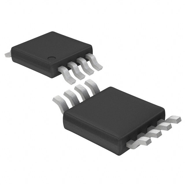
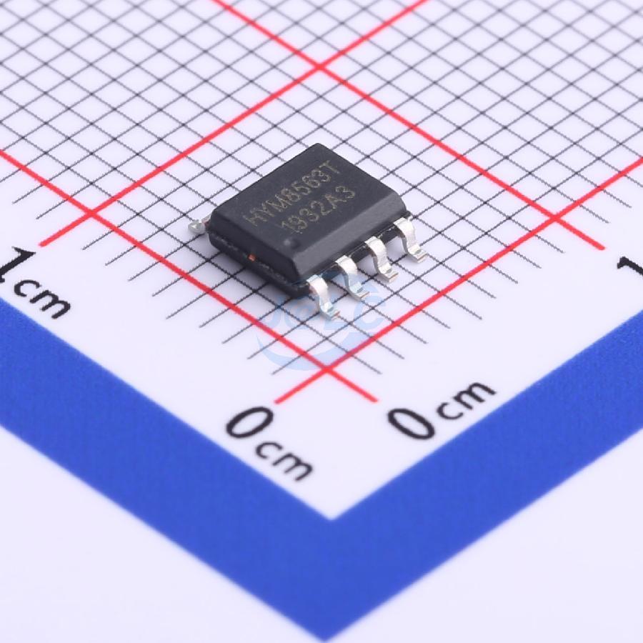
- Package: SOP-8

FREE delivery for orders over HK$250.00

Quick response, quick quotaton

Flash shipment,no worries after sales

Original channel,guarantee of the authentic products
jrc4558
The JRC4558 is a dual operational amplifier that’s great for a variety of applications. It comes in both 8-pin DIP and SOIC packages, making it versatile for through-hole or surface-mount projects. This op-amp runs on low power, making it ideal for battery-powered devices. With a wide voltage range from ±3V to ±18V, it’s suitable for many uses. It’s known for its low noise and high accuracy, making it perfect for audio amplifiers, tone controls, and signal conditioning circuits. With a good slew rate and low harmonic distortion, you can rely on it for high-fidelity audio or precise analog signal processing.
jrc4558 pinout and features
| Pin Number | Pin Name | Function |
|---|---|---|
| 1 | Offset Null 1 | Connect to an external potentiometer for offset adjustment (if required). |
| 2 | Inverting Input (Op-Amp 1) | Input for the inverting signal of the first op-amp. |
| 3 | Non-Inverting Input (Op-Amp 1) | Input for the non-inverting signal of the first op-amp. |
| 4 | V- (Negative Supply) | Connect to the negative voltage rail (or ground if single supply). |
| 5 | Offset Null 2 | Connect to an external potentiometer for offset adjustment (if required). |
| 6 | Output (Op-Amp 1) | Output of the first op-amp. |
| 7 | V+ (Positive Supply) | Connect to the positive voltage rail. |
| 8 | Output (Op-Amp 2) | Output of the second op-amp. |
| 9 | Non-Inverting Input (Op-Amp 2) | Input for the non-inverting signal of the second op-amp. |
| 10 | Inverting Input (Op-Amp 2) | Input for the inverting signal of the second op-amp. |
| 11 | Offset Null 1 | Connect to an external potentiometer for offset adjustment (if required). |
| 12 | V- (Negative Supply) | Connect to the negative voltage rail (or ground if single supply). |
| 13 | Output (Op-Amp 2) | Output of the second op-amp. |
The JRC4558 has a few key pins for proper operation. Pins 1 and 5 are for offset voltage adjustments if needed, but you can usually leave them unconnected unless you need precise calibration. Pins 2 and 3 (for Op-Amp 1) and 9 and 10 (for Op-Amp 2) are the inverting and non-inverting inputs, where you’ll feed your signals. Pins 7, 4, and 12 are for power supply connections—V+ goes to the positive supply, and V- to the negative or ground. Outputs are at pins 6 and 8, where the amplified signal is available. Just remember, the output won’t hit the supply rail but stays a few volts away.
jrc4558 equivalent op-amp
| Parameter | JRC4558 | LM358 | TLV2372 | MC34072 |
|---|---|---|---|---|
| Package Type | 8-pin DIP/SOIC | 8-pin DIP/SOIC | 8-pin DIP/SOIC | 8-pin DIP/SOIC |
| Number of Channels | Dual (2 op-amps) | Dual (2 op-amps) | Dual (2 op-amps) | Dual (2 op-amps) |
| Supply Voltage | ±3V to ±18V (6V to 36V) | ±3V to ±32V (Single or Dual) | ±2V to ±18V (Single or Dual) | ±3V to ±18V (6V to 36V) |
| Slew Rate | 0.3 V/μs | 0.3 V/μs | 0.04 V/μs | 0.3 V/μs |
| Input Offset Voltage | 3 mV | 2 mV | 2 mV | 3 mV |
| Bandwidth | 1 MHz | 1 MHz | 1 MHz | 1 MHz |
| Common-Mode Rejection | 70 dB | 70 dB | 100 dB | 90 dB |
| Package Size | 8-pin DIP/SOIC | 8-pin DIP/SOIC | 8-pin DIP/SOIC | 8-pin DIP/SOIC |
| Power Consumption | Low | Low | Low | Low |
| Applications | Audio, Signal Processing, Instrumentation | General-purpose, Low-power circuits | Precision applications, Low-power | Audio, Signal Processing, Low-noise circuits |
If you’re looking for alternatives to the JRC4558, the LM358 is a great match. It has a similar voltage range, slew rate, and bandwidth, with a slightly lower input offset voltage (2mV vs. 3mV), making it ideal for low-noise applications. The TLV2372, on the other hand, has a lower slew rate (0.04V/μs) but offers better common-mode rejection (100 dB), making it perfect for precision applications where noise rejection is key. The MC34072 is another option, offering similar features with a higher common-mode rejection (90 dB). If you need low power, the TLV2372 is a strong choice.
jrc4558 audio amplifier circuit

The circuit you’ve got here is using two JRC4558 op-amps for stereo audio, with one for the left channel and one for the right. The audio signals come in through the left and right inputs, pass through tone control (treble, mid, and bass), and then adjust the volume. The tone control lets you tweak the sound to your liking by adjusting the treble, mid, and bass with the potentiometers. After that, the volume control fine-tunes the loudness before sending the signal to the output for your speakers. This setup is common in home audio systems, giving you full control over your sound.
jrc4558 low noise amplifier usage
The JRC4558 is great for low noise amplification (LNA), especially in audio and signal processing circuits. It’s commonly used in audio systems where it helps amplify weak signals with minimal noise. For example, it’s ideal in microphone preamps, where it boosts weak audio signals before further processing. You can also use it in sensor systems, amplifying small signals without adding distortion. The JRC4558 works well in RF circuits too, improving weak radio signals while keeping noise low. It’s also useful in filter circuits, ensuring noise is filtered out while amplifying the desired signal.
jrc4558 in audio preamplifier application
The JRC4558 is a solid choice for audio preamps, thanks to its low noise and distortion. It works great for amplifying weak signals from microphones, instruments, and turntables. In a microphone preamp, for example, it boosts the signal with minimal noise, making sure the sound stays clear. It also shines in guitar pedals, amplifying the guitar’s output while preserving the tone. For turntables, it amplifies the low signal from the phono cartridge to a usable level, keeping the vinyl sound crisp. Its dual op-amp design makes it perfect for stereo systems or amplifying two signals at once.


