L9110S Arduino & Datasheet | Driver H Bridge
- Motor Type - Stepper: Bipolar
- Function: Driver - Fully Integrated, Control and Power Stage
- Applications: General Purpose
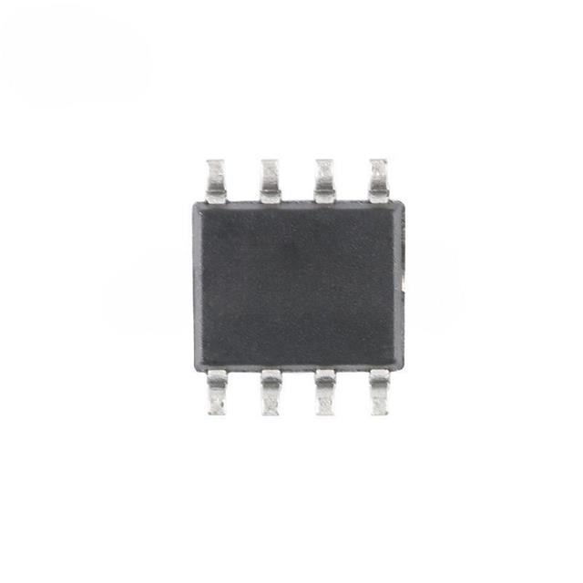
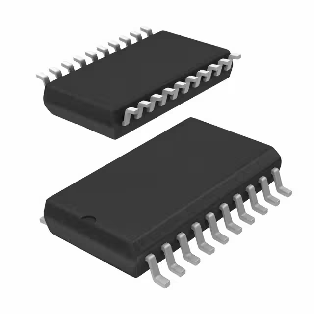
- Package: 8-SOIC (0.154", 3.90mm Width)

FREE delivery for orders over HK$250.00

Quick response, quick quotaton

Flash shipment,no worries after sales

Original channel,guarantee of the authentic products
Key Features of the L9110S Motor Driver
The L9110S is a compact and efficient dual-channel motor driver, perfect for driving small DC motors in various applications. It supports both forward and reverse motor rotation, making it ideal for simple robotics, toys, and automation projects. The L9110S operates on a voltage range of 2.5V to 12V and can provide up to 800mA per channel, allowing for moderate power control in low to mid-range motor applications. Its built-in thermal shutdown and overcurrent protection make it reliable and safe to use in long-running projects. Simple to use with minimal external components, the L9110S is a solid choice for controlling small motors in your designs.
L9110S Pinout
| Pin | Label | Description |
|---|---|---|
| 1 | VCC | Power supply pin (2.5V to 12V) for the motor driver. |
| 2 | AIN1 | Input pin for controlling the direction of motor A (forward). |
| 3 | AIN2 | Input pin for controlling the direction of motor A (reverse). |
| 4 | GND | Ground pin, connected to the system ground. |
| 5 | BIN1 | Input pin for controlling the direction of motor B (forward). |
| 6 | BIN2 | Input pin for controlling the direction of motor B (reverse). |
| 7 | VOUTA | Output pin for driving motor A. |
| 8 | VOUTB | Output pin for driving motor B. |
Using the L9110S Pinout
To use the L9110S motor driver, first connect the VCC pin (Pin 1) to your power supply (within the 2.5V to 12V range), and the GND pin (Pin 4) to the ground. To control motor A, use AIN1 (Pin 2) and AIN2 (Pin 3) to set the forward and reverse direction. Similarly, BIN1 (Pin 5) and BIN2 (Pin 6) control motor B. The VOUTA (Pin 7) and VOUTB (Pin 8) provide the output to drive the motors. Ensure the motor current does not exceed 800mA per channel to prevent overheating or damage. Properly managing the power and control signals will ensure smooth motor operation.
L9110S Equivalent Models
Here’s a comparison of equivalent motor drivers with similar packaging and performance:
| Model | Voltage Range | Output Current | Channels | Package Type | Protection Features |
|---|---|---|---|---|---|
| L9110S | 2.5V to 12V | 800mA per channel | Dual | SOP-8 | Overcurrent, Overtemperature |
| L298N | 4.5V to 46V | 2A per channel | Dual | DIP-15 | Overcurrent, Thermal Shutdown |
| TB6612FNG | 4.5V to 13.8V | 1.2A per channel | Dual | SOP-16 | Overcurrent, Overtemperature |
| DRV8833 | 2.7V to 10.8V | 1.5A per channel | Dual | HTSSOP-16 | Overcurrent, Thermal Shutdown |
Substitution Tips
When replacing the L9110S, ensure that the voltage range and current output are similar to maintain reliable motor operation. Models like the L298N offer a higher current output (2A per channel) but come in a larger DIP-15 package. The TB6612FNG is a compact alternative with slightly higher current output (1.2A) and similar protection features. The DRV8833 also offers good performance with a higher current rating of 1.5A per channel and additional thermal protection. Always check the package type and pinout compatibility before replacing to ensure the new driver fits your design.
L9110S Arduino Integration
The L9110S motor driver is easy to integrate with an Arduino for controlling small DC motors. By connecting the L9110S to the Arduino’s digital pins, you can control the motor’s direction and speed. You’ll typically use the AIN1, AIN2, BIN1, and BIN2 pins to control two motors. The Arduino will send high and low signals to these pins to drive the motors forward, reverse, or stop.
L9110S H-Bridge Arduino Code
Here’s a simple Arduino code to control the L9110S H-Bridge motor driver:
This code drives both motors forward, backward, and stops them. You can modify it to suit your specific needs, like adding PWM for speed control or using sensors for more advanced functionality.
L9110S Motor Driver Circuit Overview
The L9110S is a compact dual-channel motor driver IC designed for driving small DC motors and stepper motors. It utilizes an H-bridge configuration to control the direction and speed of motors, making it ideal for applications like robotics and automation.
Circuit Diagram
Circuit Analysis
In this typical application circuit:
-
VCC (Pin 1 & Pin 3): Connected to the positive terminal of the power supply (2.5V to 12V).
-
GND (Pin 2 & Pin 5): Connected to the ground of the power supply.
-
A-IA (Pin 4) & A-IB (Pin 5): Input pins for controlling motor A’s direction.
-
B-IA (Pin 6) & B-IB (Pin 7): Input pins for controlling motor B’s direction.
-
OA (Pin 8) & OB (Pin 9): Output pins connected to the motor terminals.
By applying high and low signals to the input pins (A-IA, A-IB, B-IA, B-IB), you can control the rotation direction of the motors. For example, setting A-IA high and A-IB low will make motor A rotate in one direction, while setting A-IA low and A-IB high will reverse its direction. Similarly, controlling B-IA and B-IB will manage motor B’s rotation.
Important Considerations
-
Input Voltage: Ensure the input voltage is within the specified range (2.5V to 12V) to prevent damage to the IC.
-
Current Rating: The L9110S can supply up to 800mA of continuous current per channel. Exceeding this can cause overheating or failure.
-
PWM Control: For speed control, Pulse Width Modulation (PWM) signals can be applied to the input pins, adjusting the duty cycle to vary motor speed.
-
Heat Dissipation: Under high load conditions, the IC may generate heat. Ensure adequate ventilation or heat sinking to maintain reliable operation.
This simple and efficient circuit is ideal for powering low-current devices like microcontrollers, sensors, and small LEDs.
