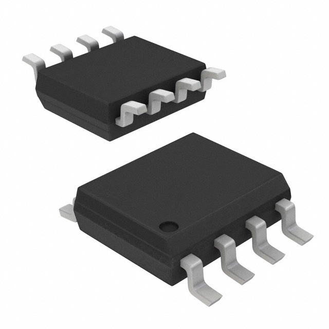
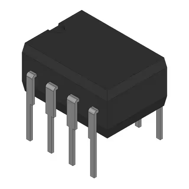
LM393N comparator circuit, pinout vs lm393p Texas Instruments
- Type: General Purpose
- Number of Elements: 2
- Output Type: CMOS, DTL, ECL, MOS, Open-Collector, TTL
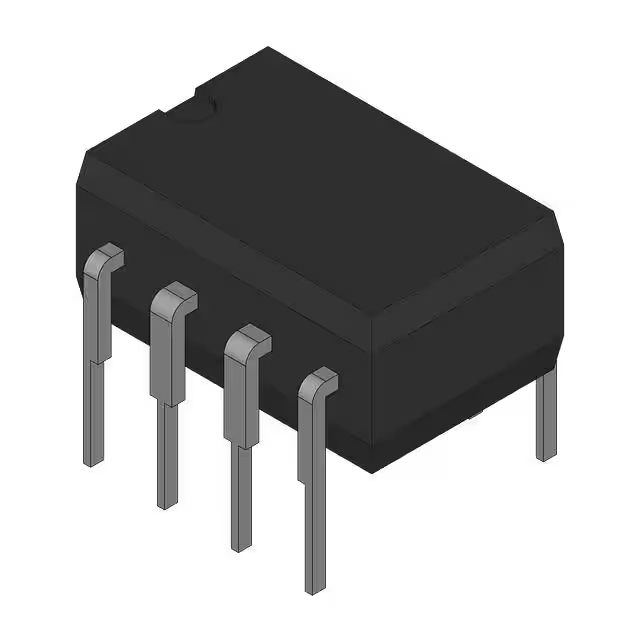
- Package: 8-DIP (0.300, 7.62mm)

FREE delivery for orders over HK$250.00

Quick response, quick quotaton

Flash shipment,no worries after sales

Original channel,guarantee of the authentic products
Key Features of the LM393N Comparator
The LM393N is a versatile dual comparator, perfect for a variety of signal comparison tasks. With a wide input voltage range of 2V to 36V, it’s suitable for both single and dual power supply systems. It features an open-collector output, making it easy to interface with TTL and CMOS logic circuits. The LM393N is designed to operate with low power consumption, making it ideal for battery-operated applications. It also includes built-in hysteresis, which helps prevent false triggering in noisy environments. Whether you’re working with simple logic circuits or complex analog systems, the LM393N provides reliable and efficient performance.
LM393N Pinout
| Pin | Label | Description |
|---|---|---|
| 1 | Output (A) | Open collector output for comparator A. Needs a pull-up resistor to work properly. |
| 2 | Inverting Input (A) | Negative input for comparator A (signal input). |
| 3 | Non-Inverting Input (A) | Positive input for comparator A (signal input). |
| 4 | GND | Ground pin, connected to the system ground. |
| 5 | Non-Inverting Input (B) | Positive input for comparator B (signal input). |
| 6 | Inverting Input (B) | Negative input for comparator B (signal input). |
| 7 | Output (B) | Open collector output for comparator B. Needs a pull-up resistor to work properly. |
| 8 | VCC | Positive power supply pin (2V to 36V). |
Using the LM393N Pinout
To use the LM393N, connect the VCC pin (Pin 8) to your power supply and GND (Pin 4) to the common ground. The two comparators inside the LM393N are controlled by applying signals to the Inverting Input (Pins 2 and 6) and Non-Inverting Input (Pins 3 and 5) for each comparator. The output pins (Pins 1 and 7) are open collector, so you will need to connect a pull-up resistor to get a high signal when the comparator is active. Be sure to avoid exceeding the voltage limits to prevent damaging the IC.
LM393N Equivalent Models
Here’s a comparison of equivalent comparators with similar packaging and performance:
| Model | Voltage Range | Output Type | Response Time | Package Type | Input Voltage Range |
|---|---|---|---|---|---|
| LM393N | 2V to 36V | Open Collector | 1µs | DIP-8 | 0V to 36V |
| LM339 | 2V to 36V | Open Collector | 1µs | DIP-14 | 0V to 36V |
| TLV3201 | 1.8V to 5.5V | Open Collector | 1µs | SOIC-8 | 0V to 5.5V |
| LM2903 | 3V to 36V | Open Collector | 1µs | DIP-8 | 0V to 36V |
Substitution Tips
When replacing the LM393N, ensure the voltage range and output type are compatible with your circuit. For example, the LM339 is a good alternative with a similar output and response time but comes in a larger DIP-14 package. The TLV3201 is ideal if you’re working with lower voltages and need a more compact SOIC-8 package. If you need a dual comparator similar to the LM393N but with lower supply requirements, the LM2903 is a suitable replacement. Always check the input voltage range to ensure the replacement fits your application’s voltage requirements.
LM393N Ham Radio Projects
The LM393N comparator is a great component for building various ham radio projects. Its low cost, reliability, and open-collector output make it perfect for signal detection, frequency measurement, and filtering applications in ham radio circuits. You can use the LM393N for building simple squelch circuits, audio tone generators, or frequency counters. It’s also ideal for voltage level detection, ensuring your equipment operates within safe ranges. With its versatility and ease of integration into different designs, the LM393N is a popular choice among ham radio enthusiasts for enhancing the functionality and performance of radio systems.
LM393N Overvoltage Protection Circuit
Here’s a practical application of the LM393N comparator: an overvoltage protection circuit. This circuit monitors the input voltage and triggers a relay to disconnect the load if the voltage exceeds a preset threshold, protecting sensitive components from damage.
Circuit Diagram
Circuit Analysis
-
LM393N Comparator: The LM393N is configured as a voltage comparator. The non-inverting input (Pin 3) receives a reference voltage, while the inverting input (Pin 2) is connected to the monitored voltage. When the monitored voltage exceeds the reference, the output (Pin 1) switches states.
-
Relay Driver: The open-collector output of the LM393N (Pin 1) is used to drive a transistor, which in turn controls a relay. This relay disconnects the load when overvoltage is detected.
-
Protection Diodes: Diodes are placed across the relay coil to protect against voltage spikes when the relay is de-energized.
-
Power Supply: The circuit operates with a 5V DC supply, suitable for low-power applications.
Important Considerations
-
Pull-up Resistor: Since the LM393N has an open-collector output, a pull-up resistor is required to ensure proper voltage levels at the output.
-
Relay Specifications: Choose a relay with a coil voltage matching your supply and a contact rating suitable for your load.
-
Component Ratings: Ensure all components are rated for the voltages and currents in your application to prevent damage.
This overvoltage protection circuit is simple to implement and provides an effective means of safeguarding electronic devices from voltage surges.
