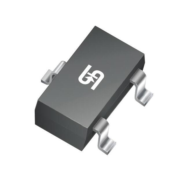
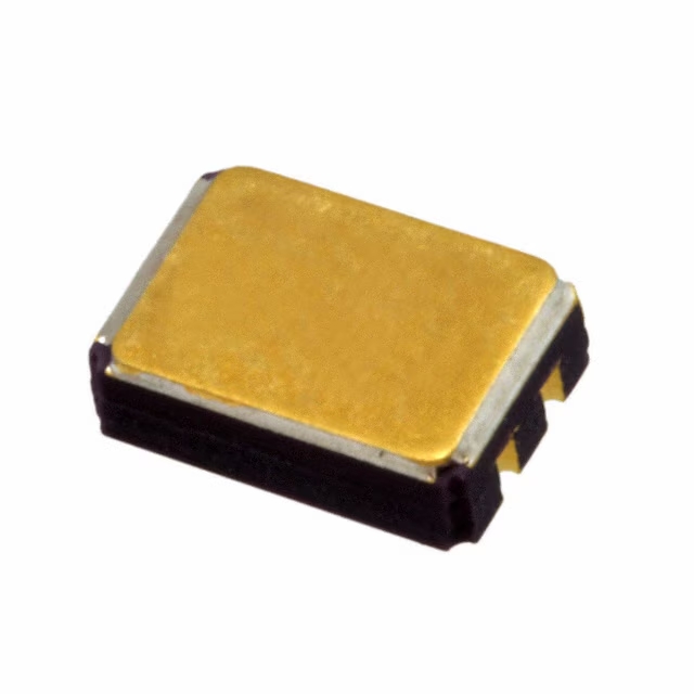
MMBT2907ALT1G | Datasheet & PDF | On Semiconductor | Spice Model onsemi
- Transistor Type: PNP
- Current-Collector(Ic)(Max): 600 mA
- Voltage-Collector Emitter Breakdown (Max): 60 V
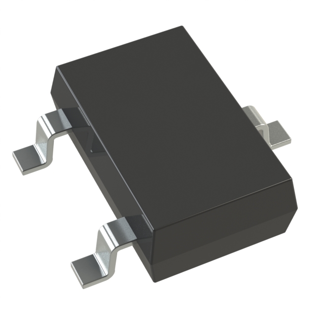
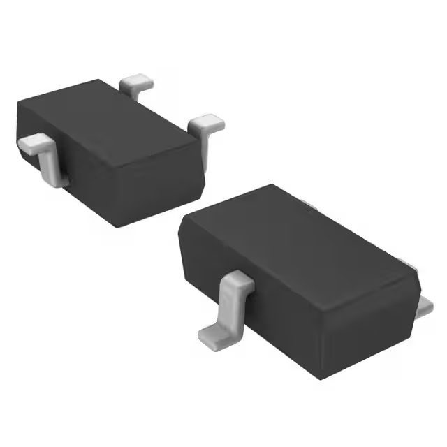
- Package: TO-236-3, SC-59, SOT-23-3

FREE delivery for orders over HK$250.00

Quick response, quick quotaton

Flash shipment,no worries after sales

Original channel,guarantee of the authentic products
MMBT2907ALT1G
The MMBT2907ALT1G is a PNP transistor that’s great for general applications like switching and amplification. It comes in a compact SOT-23 package, making it easy to fit into your design. The transistor can handle a maximum collector-emitter voltage of 60V and a maximum collector current of 200mA. It has a DC current gain (hFE) between 100 and 300, meaning it can amplify signals well, depending on the current. With a power dissipation of 500mW, it’s designed to handle decent power without overheating. It’s fast when switching, which is ideal for high-speed circuits, and its low saturation voltage makes it perfect for low-voltage systems. The MMBT2907ALT1G operates in a wide temperature range from -55°C to +150°C, so it works reliably in various environments. You’ll commonly find it in low-power switching, signal amplification, and as a general-purpose transistor in electronic circuits.
MMBT2907ALT1G Pinout and Marking

| Pin Number | Pin Name | Pin Description |
|---|---|---|
| 1 | Collector (C) | The collector pin connects to the load or the high potential side of the circuit. This is where the current enters the transistor. |
| 2 | Base (B) | The base pin controls the transistor’s switching action. A small current input to this pin turns the transistor on or off. |
| 3 | Emitter (E) | The emitter pin is where current flows out of the transistor when it is on. It is typically connected to the ground or low potential side of the circuit. |
When using the MMBT2907ALT1G transistor, make sure the collector voltage stays within the 60V maximum rating, and don’t exceed the 200mA current limit. The base pin controls the current between the collector and emitter. A small current at the base will switch the transistor on, and the base-emitter voltage (V_BE) typically needs to be around 0.7V to fully turn the transistor on. The emitter is usually connected to the ground or low side of the circuit, and when the transistor is on, the current flows from the collector to the emitter. It’s also important to avoid exceeding the maximum base-emitter voltage of 5V to protect the transistor from damage. Lastly, keep the power dissipation under 500mW to prevent overheating and ensure reliable operation.
MMBT2907ALT1G Equivalent NPN Transistor

| Parameter / Model | MMBT2907ALT1G | BCX70P | PN2907A | MMBT3906 | BC807-40 |
|---|---|---|---|---|---|
| Transistor Type | PNP | PNP | PNP | PNP | PNP |
| Package | SOT-23 | SOT-23 | TO-92 (Through-hole) | SOT-23 | SOT-23 |
| Max Collector Current (Ic) | 600mA | 100mA | 600mA | 200mA | 100mA |
| Max Vceo Voltage | 40V | 45V | 40V | 40V | 45V |
| hFE @ Ic | 100-800 @ 10mA | 110-800 @ 2mA | 50-300 @ 10mA | 30-300 @ 2mA | 250-800 @ 100mA |
| Max Power Dissipation (Pd) | 300mW | 300mW | 625mW | 300mW | 300mW |
| Transition Frequency (ft) | 100MHz | 100MHz | 100MHz | 250MHz | 100MHz |
| Typical Application | General Switching | Old Design, Through-hole Applications | High-Frequency, Low Noise | General Switching | High β Value, Low Noise Applications |
When choosing a replacement for the MMBT2907ALT1G, here are some things to keep in mind:
For circuits that need to drive loads over 200mA, like LEDs or small motors, the MMBT2907ALT1G is a better option. The MMBT3906 and BC807-40 aren’t suitable for high-current applications. If you’re working with high-frequency or amplification tasks, the MMBT3906 has a higher ft (250MHz), making it a good fit for audio amplifiers or high-speed circuits, while the MMBT2907ALT1G is more suited for mid- to low-frequency applications.
The BC807-40 has a higher β value at 100mA, but be careful with the bias current design. On the other hand, the MMBT2907ALT1G has a high β value even at 10mA, making it great for small-signal amplification.
MMBT2907ALT1G Switching Circuit Diagram

Let me break down this circuit for you. There are two power supplies here: a +15V and a -6V. The +15V connects to the collector of the MMBT2907ALT1G transistor through a 1kΩ resistor, while the emitter goes to -6V via a 37Ω resistor.
The base gets its signal through another 1kΩ resistor. You’ll notice a 1N916 diode between the base and emitter – it’s there to guard against reverse voltage.
There’s also a 50Ω resistor tied to ground, which probably helps stabilize things or act as a load.
On the input side, there’s a -30V pulse lasting 200ns hitting the base. When that negative pulse hits, it pulls the base voltage down enough to switch the transistor on. Since it’s an NPN type, this drop lets current flow from collector to emitter.
Without that pulse, the transistor stays off, blocking most current. This setup is common in fast-switching applications where quick response matters.
MMBT2907ALT1G Amplifier Circuit Example

When working with the MMBT2907ALT1G transistor, it’s important to understand its basic function. It’s an NPN bipolar transistor, commonly used for audio and RF signal amplification. It can handle moderate power levels, with current ratings in the hundreds of milliamps and voltage limits in the tens of volts.
In a typical amplifier setup, the input signal goes through a resistor before reaching the base. This resistor controls the base current and sets the right bias point. The transistor uses its gain to turn this small input into a larger current flow at the collector.
That change in current creates a voltage shift across the collector resistor, which gives you the amplified output. Choosing the right resistor values affects how much the signal is boosted.
Setting up the bias correctly helps keep the transistor operating in its linear range, which means cleaner amplification without distortion.
MMBT2907ALT1G Base Resistor Sizing
If you’re working with the MMBT2907ALT1G PNP transistor and need to size the base resistor, the key is to think about the current the transistor will handle, its gain (β), and the input voltage. To get the right resistor value, you first figure out how much current is needed for the base. Then, using the voltage you’re applying to the base and the typical base-emitter voltage of 0.7V, you calculate the resistor.
For example, if your circuit requires 10mA of current and you’re using a 5V input, you would pick a resistor value that makes sure the base current is enough for the transistor to work properly. In this case, something around 43kΩ should do the trick. You can adjust this value depending on your setup.
MMBT2907ALT1G Load Switching Application
The MMBT2907ALT1G is a PNP transistor you can use to switch things like an LED, motor, or relay. To get it working, you simply control the base current with a resistor. When you apply a base current, the transistor turns on (saturation), allowing current to flow through the load. When you stop the base current, the transistor turns off (cutoff), and no current flows.
For example, to switch an LED: connect the LED’s anode to a positive voltage, and the cathode to the transistor’s collector. The base goes to your microcontroller’s output pin with a small resistor (like 1kΩ) in between. When the microcontroller outputs a HIGH signal (e.g., 5V), the LED lights up. When it’s LOW, the LED goes dark.






,TO-226_straightlead.jpg)

