
PL2303GC driver & USB to serial
- Brands: Prolific Tech
- Download: -
- Price: inquiry
- In Stock: 6848
- Voltage - Supply: -
- Applications Function: -
- Protocol: -
- Package: -


FREE delivery for orders over HK$250.00

Quick response, quick quotaton

Flash shipment,no worries after sales

Original channel,guarantee of the authentic products
pl2303gc
This chip you’re using supports USB 2.0 full-speed communication and also works with older USB 1.1 devices. It’s super easy to use since the USB transceiver is built right in, meaning no external crystal is needed.
It also handles RS-232 UART communication. You can configure data bits, stop bits, and parity easily, and the baud rate ranges widely from 75bps to 12Mbps, covering practically every use case you might have.
Operating voltage is flexible—between 3.3V and 5V—and its low-power design is perfect for portable devices. You get extra GPIO pins, giving you more control over external equipment.
Packaging options like SSOP-28 or QFN keep your PCB layouts compact. Plus, drivers for Windows, Linux, and Mac OS are widely available, making compatibility a breeze. It even includes built-in ESD protection for improved durability and reliability.
pl2303gc pinout and wiring
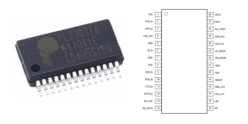
| Pin Number | Pin Name | Type | Default Function | Description |
|---|---|---|---|---|
| 1 | TXD / GPA0 | Output | UART Transmit Data | Configurable GPIO |
| 2 | DTR_N / GPA4 | Output | Data Terminal Ready | Configurable GPIO |
| 3 | RTS_N / GPA2 | Output | Request To Send | Configurable GPIO |
| 4 | VDD_IO | Power | I/O Power Input | 1.8V – 5V |
| 5 | RXD / GPA1 | Input | UART Receive Data | Configurable GPIO |
| 6 | RI_N / GPA7 | Input | Ring Indicator | Configurable GPIO |
| 7 | NC | – | No Connection | Leave unconnected |
| 8 | GPB7 / TXEN | Output | Transmit Enable | Configurable GPIO |
| 9 | DSR_N / GPA5 | Input | Data Set Ready | Configurable GPIO |
| 10 | DCD_N / GPA6 | Input | Data Carrier Detect | Configurable GPIO |
| 11 | CTS_N / GPA3 | Input | Clear To Send | Configurable GPIO |
| 12 | GPB6 / SUSP_N | Output | Suspend Indicator | Configurable GPIO |
| 13 | GPB3 | I/O | GPIO | Multipurpose GPIO |
| 14 | GPB2 | I/O | GPIO | Multipurpose GPIO |
| 15 | DP | I/O | USB Data+ | USB Interface |
| 16 | DM | I/O | USB Data- | USB Interface |
| 17 | VO_33 | Power | 3.3V LDO Output | Optional external power supply |
| 18 | GND | Power | Ground | Ground connection |
| 19 | RESET_N | Input | Reset Signal | Active Low |
| 20 | VIN | Power | USB Power Input | Typically 5V |
| 21 | NC | – | No Connection | Leave unconnected |
| 22 | GPB0 | I/O | GPIO | Multipurpose GPIO |
| 23 | GPB1 | I/O | GPIO | Multipurpose GPIO |
| 24 | GPB4 | I/O | GPIO | Multipurpose GPIO |
| 25 | GPB5 | I/O | GPIO | Multipurpose GPIO |
| 26 | NC | – | No Connection | Leave unconnected |
| 27 | XI | Input | External Crystal Input | Optional |
| 28 | XO | Output | External Crystal Output | Optional |
When working with the PL2303GC, make sure the VIN pin connects directly to the USB’s 5V line. Set the I/O voltage (VDD_IO) between 1.8V and 5V depending on your device. The internal 3.3V regulator (VO_33) can power small external circuits, but don’t overload it.
For USB wiring, connect DP and DM lines through 27Ω resistors and add a 0.1µF capacitor close to the chip to clean up signals. For UART communication, connect TXD and RXD to the opposite RXD and TXD on the device. Match logic levels carefully. Other control signals like RTS or CTS can connect as needed.
GPIO pins (GPAx, GPBx) offer various features like LED indicators or I2C—use the OTPROM tool or EEPROM for configuring. Unused GPIO pins work best when set as inputs with pull-up or pull-down resistors.
The chip includes a built-in 96MHz clock, so usually there’s no need for an external crystal. Package options are SSOP-28 and UQFN-24, choose according to your PCB layout.
pl2303gc equivalent usb uart converter
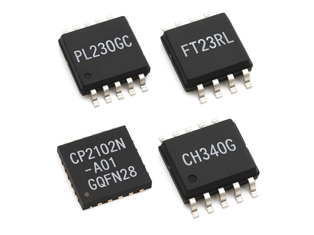
| Parameter | PL2303GC | FT232RL | CP2102N-A01-GQFN28 | CH340G |
|---|---|---|---|---|
| Manufacturer | Prolific | FTDI | Silicon Labs | WCH |
| Package | SSOP-28 | SSOP-28 | QFN-28 (Non-SSOP-28) | SSOP-16 (Non-SSOP-28) |
| Max Baud Rate | 12 Mbps | 3 Mbps | 3 Mbps | 2 Mbps |
| Voltage Support | 1.8V–5V I/O, internal LDO outputs 3.3V | 3.3V I/O, internal LDO outputs 3.3V | 1.8V–3.3V I/O, internal LDO outputs 3.3V | 3.3V–5V I/O, internal LDO outputs 3.3V |
| GPIO Pins | Up to 16 (configurable) | 4 (CBUS0–CBUS3, configurable) | 4 (configurable) | None |
| Driver Support | Windows, Linux, macOS, Android | Windows, Linux, macOS | Windows, Linux, macOS | Windows, Linux |
| Internal EEPROM/OTP | 256-byte OTPROM, programmable via USB | Internal EEPROM, programmable via USB | Internal OTP, programmable via USB | None |
| Special Features | Supports RS232/RS485/RS422, battery charging detection | CBUS pins for LED indication, clock output, etc. | Supports battery charging detection, remote wake-up | Low-cost, suitable for low-speed communication |
| Typical Applications | Industrial control, embedded systems, high-speed communication | General UART communication, embedded systems, USB-UART cables | Industrial control, embedded systems, USB-UART modules | Education, development boards, cost-effective devices |
When choosing alternatives to PL2303GC, it’s important to check package compatibility. For example, CP2102N uses a QFN-28 package, while CH340G comes in SSOP-16, so make sure your PCB layout matches.
Driver support varies. FT232RL and CP2102N have reliable drivers that install easily across most operating systems. CH340G might require manual driver setup and can sometimes cause compatibility headaches.
If high-speed communication or multiple GPIO pins matter for your project, PL2303GC or CP2102N will work better. If budget is tight and communication speeds aren’t critical, CH340G is affordable and effective.
Also, keep an eye on availability. FT232RL often experiences supply shortages or price fluctuations, making long-term planning tricky. Consider supply stability before deciding.
pl2303gc serial communication circuit
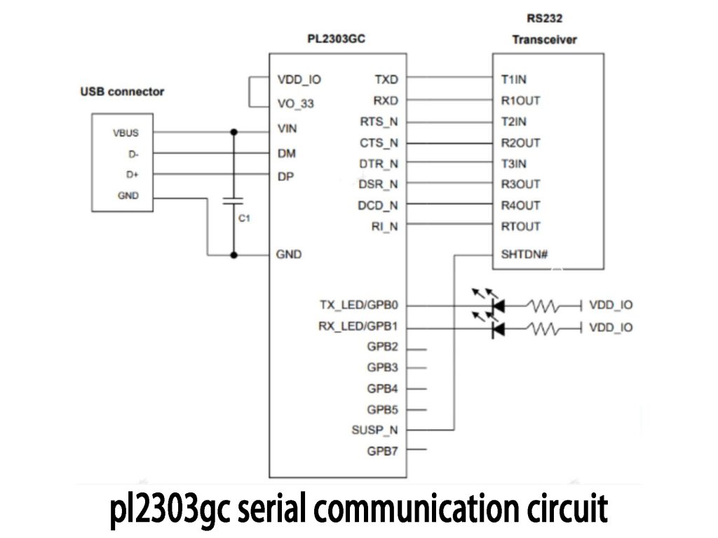
This circuit shows how to set up a USB-to-RS232 interface using a PL2303GC chip. It mainly has three sections: the USB connector, the PL2303GC chip itself, and an RS232 transceiver.
The USB connector supplies 5V power and connects data lines (D+ and D-) directly to the PL2303GC. The chip takes this USB data and converts it into TTL-level serial signals like TXD, RXD, and flow-control lines such as RTS and CTS. The TX_LED and RX_LED pins connect to LEDs to show you when data is sent or received. There’s also a built-in 3.3V regulator (VO_33) that powers the internal logic or small external circuits.
Next, an RS232 transceiver chip converts the PL2303GC’s TTL signals into standard RS232 signals, making it easy to hook up standard RS232 devices.
When connected to a PC via USB, the chip receives power and communicates over USB, converting data between USB and RS232, allowing seamless communication between computers and serial devices.
pl2303gc arduino connection guide
If you’re working with Arduino boards like the Pro Mini or Nano that don’t have built-in USB ports, using a PL2303GC USB-to-serial converter can save a lot of hassle. Just connect TX on the PL2303GC to RX (pin 0) on Arduino, RX to TX (pin 1), and make sure both share a common ground (GND). Match the Arduino’s voltage (3.3V or 5V) with the PL2303GC’s VO_33 or VDD_IO pin.
In the Arduino IDE, set your board type under “Tools → Board,” choose the correct COM port under “Tools → Port,” and pick a common baud rate like 9600 in your sketch (Serial.begin(9600);). Upload a simple program to test communication—sending “Hello from Arduino!” repeatedly works well.
Make sure the PL2303 drivers are installed on your computer for smooth connection. It’s perfect for programming Arduinos without built-in USB, debugging your projects, or collecting data easily.
pl2303gc usb ttl interface project
Here’s how the PL2303GC chip works: First, the computer sends data through its USB port (VBUS, D+, D-, GND) to the chip. Inside the chip, the USB signals are converted into simple UART signals at TTL voltage levels. Then, these TTL signals (TX and RX pins) directly connect to your device, like an Arduino or other microcontrollers, letting them communicate easily.
This setup makes it simple to debug or upload code to devices without USB ports. It also gives reliable, fast communication (up to 12Mbps), perfect for real-time data monitoring or embedded system debugging.
Common uses include Arduino, ESP32, or STM32 development boards, serial device maintenance, data acquisition setups, or general-purpose USB-to-serial adapters.
Just keep an eye on voltage levels—make sure your TTL logic is 3.3V or 5V to avoid damage. Adding decoupling capacitors and ESD protection devices also helps keep things running stable and safe.
More Like This

LTC2914CDHC-2#PBF
Analog Devices Inc.

ADM695ARZ
Analog Devices Inc.

DS1706PESA+
Analog Devices Inc./Maxim Integrated

MAX818LCUA+
Analog Devices Inc./Maxim Integrated

DS1231-35+
Analog Devices Inc./Maxim Integrated
MAX706TESA+
Analog Devices Inc./Maxim Integrated

MAX16001ATE+
Analog Devices Inc./Maxim Integrated

MAX6338BUB+
Analog Devices Inc./Maxim Integrated

MAX16002BTC+
Analog Devices Inc./Maxim Integrated
MAX807LCPE+
Analog Devices Inc./Maxim Integrated

DS1831AS+
Analog Devices Inc./Maxim Integrated

MAX6714DUB+
Analog Devices Inc./Maxim Integrated
Also Add to Cart
ISPGAL22V10AB-75LNI
Lattice Semiconductor Corporation

EL5244CSZ-T13
Elantec

M74HC190RM13TR
STMicroelectronics

UCC28742DBVR
Texas Instruments

TLC555ID
Texas Instruments

UCC3915DPTR
Texas Instruments

SNJ54H05J
Texas Instruments

SN65LVDS301ZXHR
Texas Instruments

MAX3600ACTL+T
Analog Devices Inc./Maxim Integrated

INA199B2DCKR
Texas Instruments

TPS65235-1RUKT
Texas Instruments

HV2701FG-G-M931
Microchip Technology
Related Products
LTC2914CDHC-2#PBF
Analog Devices Inc.
ADM695ARZ
Analog Devices Inc.
DS1706PESA+
Analog Devices Inc./Maxim Integrated
MAX818LCUA+
Analog Devices Inc./Maxim Integrated
DS1231-35+
Analog Devices Inc./Maxim Integrated
MAX706TESA+
Analog Devices Inc./Maxim Integrated
MAX16001ATE+
Analog Devices Inc./Maxim Integrated
MAX6338BUB+
Analog Devices Inc./Maxim Integrated
MAX16002BTC+
Analog Devices Inc./Maxim Integrated
MAX807LCPE+
Analog Devices Inc./Maxim Integrated
DS1831AS+
Analog Devices Inc./Maxim Integrated
MAX6714DUB+
Analog Devices Inc./Maxim Integrated
MAX16000ETC+
Analog Devices Inc./Maxim Integrated

MAX6338PUB+
Analog Devices Inc./Maxim Integrated
MAX702CSA+
Analog Devices Inc./Maxim Integrated
ICL7665AESA+
Analog Devices Inc./Maxim Integrated

ADM694ANZ
Analog Devices Inc.
MAX706SCUA+
Analog Devices Inc./Maxim Integrated

MAX6714BUB+
Analog Devices Inc./Maxim Integrated
MAX705CUA+
Analog Devices Inc./Maxim Integrated

MAX699CWE+
Analog Devices Inc./Maxim Integrated
MAX6302ESA+
Analog Devices Inc./Maxim Integrated
MAX701CPA+
Analog Devices Inc./Maxim Integrated

MAX8215CPD+
Analog Devices Inc./Maxim Integrated
MAX6302CSA+
Analog Devices Inc./Maxim Integrated
MAX6301CUA+
Analog Devices Inc./Maxim Integrated
MAX699CPA+
Analog Devices Inc./Maxim Integrated

TPS3307-25DGN
Texas Instruments
MAX709RESA+
Analog Devices Inc./Maxim Integrated

TLC7733IPW
Texas Instruments
Please send RFQ , we will respond immediately.
