
PT2399 datasheet & delay | best delay chip
- Brands: PTC(Princeton Tech)
- Download: -
- Price: inquiry
- In Stock: 18302
- Type: -
- Operating Temperature: -
- Interface: -
- Package: DIP-16


FREE delivery for orders over HK$250.00

Quick response, quick quotaton

Flash shipment,no worries after sales

Original channel,guarantee of the authentic products
#6 PT2399 Delay | Pedalboard Sound Tests
Pt2399
If you’re working on audio effects, you might wanna check out the PT2399 delay chip—it’s pretty popular, especially among guitar pedal builders, karaoke gear, and DIY audio projects. What’s cool about this chip is how it blends digital delay processing with a warm analog-like sound, giving you that classic echo without the hassle.
You can easily tweak the delay time just by hooking up an external resistor or a potentiometer—anywhere from a quick slapback of a few milliseconds up to about 340ms. Plus, there’s a built-in low-pass filter that keeps background noise low, helping you get cleaner sound quality.
It runs comfortably between 4.5V and 5.5V—5V being ideal—so it’s great if you’re powering your project with standard low-voltage setups. With integrated oscillators, you won’t need a ton of extra components, making your circuit simple and your PCB tidy.
Given how affordable and easy-to-use it is (available in DIP and SOP packages), the PT2399 is an awesome choice for your next DIY audio effect or bulk project.
Pt2399 Pinout
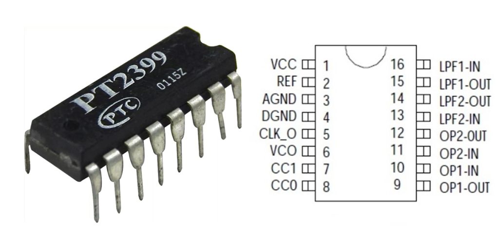
| Pin Number | Pin Name | Description |
|---|---|---|
| 1 | VCC | Positive Power Input (Typical 5V) |
| 2 | REF | Reference Voltage Output (~2.5V, for Bias Voltage) |
| 3 | AGND | Analog Ground |
| 4 | DGND | Digital Ground |
| 5 | CLK_O | Clock Oscillation Output (Typically connected to resistor for CLK_O delay adjustment) |
| 6 | VCO | Voltage-Controlled Oscillator Control Pin (Adjust frequency via external resistor) |
| 7 | CC1 | Internal Filter Capacitor Connection Pin 1 (External filter capacitor) |
| 8 | CC0 | Internal Filter Capacitor Connection Pin 0 (External filter capacitor) |
| 9 | OP1-OUT | Operational Amplifier 1 Output |
| 10 | OP1-IN | Operational Amplifier 1 Input |
| 11 | OP2-IN | Operational Amplifier 2 Input |
| 12 | OP2-OUT | Operational Amplifier 2 Output |
| 13 | LPF2-IN | Internal Low-Pass Filter 2 Input |
| 14 | LPF2-OUT | Internal Low-Pass Filter 2 Output |
| 15 | LPF1-OUT | Internal Low-Pass Filter 1 Output |
| 16 | LPF1-IN | Internal Low-Pass Filter 1 Input |
When you’re wiring up the PT2399 delay chip, there are a few things to keep in mind to make sure you get the best sound possible. First off, always power it with a stable 5V DC supply, and be careful with the ground connections—analog (AGND) and digital (DGND) grounds should ideally meet at just one spot on your PCB to reduce noise.
The REF pin outputs around 2.5V and is meant strictly as an internal reference voltage. Don’t use it for powering external stuff, or you’ll risk messing up your signal quality.
For controlling delay times, you’ll focus on the CLK_O and VCO pins. Connect them with an external resistor or a potentiometer, typically between 10kΩ and 50kΩ, to set your desired delay length.
Choosing the right filter capacitors (CC1 and CC0) really matters too. Stick with recommended values (around 0.1μF to 0.47μF) to ensure clear audio with minimal background hiss.
Finally, the chip comes with two built-in op-amps (OP1 and OP2), perfect for mixing and feedback loops—just make sure you hook them up carefully to avoid distortion or unwanted oscillation.
Pt2399 Equivalent


| Parameter | PT2399 | PT2395 | PT2396 | V3205SD | MN3207 |
|---|---|---|---|---|---|
| Package Type | DIP-16 | DIP-40 | DIP-24 | DIP-8 | DIP-8 |
| Delay Time Range | 30ms – 340ms | Up to ~800ms | 12ms – 192ms | Up to ~204ms | Up to ~51ms |
| Internal Memory | Built-in Digital Memory (44Kb) | External DRAM | Built-in Digital Memory (48Kb) | Analog BBD | Analog BBD |
| Control Method | External resistor adjustment | Voltage control | Serial Data Communication (MCU control required) | External clock control | External clock control |
| Operating Voltage | 5V | 5V | 5V | 5V | 5V |
| Circuit Complexity | Simple, fewer external components | Complex, requires external memory | Moderately complex, MCU required | Complex, external clock and filters required | Moderately complex, external clock and filters required |
| Sound Features | Digital delay with warm analog tone | Digital delay, long delay achievable | Digital delay, programmable control | Analog delay, classic warm tone | Analog delay, suitable for short delays |
| Typical Applications | DIY guitar pedals, karaoke audio | Professional delay effects, long delay requirements | Digital audio equipment, smart controlled delays | Vintage-style guitar pedals | Chorus, flanger pedals |
If you’re looking to swap out your delay chip, the PT2399 is still your best bet for most DIY projects. It’s affordable, easy to hook up, and keeps your circuit simple.
Now, say you want longer delay times—then the PT2395 could be your pick. Just know you’ll have to add some external DRAM, making your setup a bit more complex.
If programmable delays controlled by a microcontroller sound like your thing, consider the PT2396. But keep in mind, you’ll need to get comfortable with writing some code.
And if you’re chasing that classic, warm analog sound from old-school pedals, chips like the V3205SD or MN3207 might suit you better. These Bucket Brigade Devices deliver those vintage-style echoes you love, but you’ll need extra circuitry for clocks and filtering, which means more detailed planning.
Ultimately, your choice comes down to balancing your project’s complexity, delay length, and the sound character you’re after.
Pt2399 Delay Circuit For Guitar Pedal
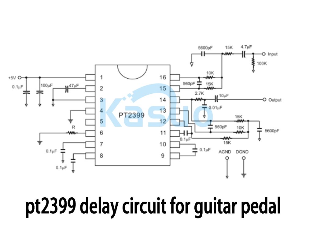
If you’re thinking about building your own guitar delay pedal, this PT2399 circuit is a great place to start. The PT2399 is a neat chip—it blends digital processing with an analog-style sound, giving you that classic echo you might recognize from vintage gear. The diagram here shows a straightforward setup using a stable 5V supply, with some extra capacitors to keep your sound clean and free from unwanted noise.
Your guitar signal first passes through some carefully chosen capacitors and resistors, prepping it nicely for the delay effect. By tweaking the potentiometer attached to pin 6, you can easily dial in the perfect delay time for your playing style. On the output side, there’s a filtering stage to make sure the echoes stay warm and clear without harsh high-frequency noise.
Plus, the chip’s built-in op-amps and external feedback circuit create those lush, repeating echoes that guitarists love, perfect for both live performances and studio recordings.
Pt2399 Reverb Circuit Example

If you’re planning to build your own reverb pedal with the PT2399 chip, here’s how it works in simple terms. First, your guitar signal goes through a capacitor and resistor network into a MOSFET transistor (usually a 2N7000). This splits the signal into two versions—one original, one inverted—which helps create a richer sound later on.
The heart of the pedal is the PT2399 chip itself. It uses digital processing to delay your signal, but it still sounds nicely analog. You can control the delay length easily with a knob (potentiometer VR1, around 20kΩ), tweaking how long your reverb echoes last. Small capacitors and resistors clean up the signal, keeping unwanted noise out.
At the output, you use two more knobs—one for adjusting the original sound level (VR4) and another for blending in the reverb effect (VR3). There’s even a feedback knob (VR2) for fine-tuning how long your echoes linger.
Lastly, there’s a footswitch included, letting you easily switch your reverb effect on and off during a performance, giving you full control on stage.
More Like This

MC5430F
Motorola

JD54LS51BCA
National Semiconductor

USPLSI2032VE-110LB49
Lattice Semiconductor Corporation
74S22PC
Rochester Electronics, LLC

9504DC
National Semiconductor

9005PC
National Semiconductor

9007DC
National Semiconductor
9004DC
National Semiconductor

SN74HC804DWR
Texas Instruments
SN700863DWR
Texas Instruments
4001BDMQB
National Semiconductor
54F02FMQB
National Semiconductor
Also Add to Cart

HEF40244BP,652
NXP USA Inc.
AOZ1270AQI
Alpha & Omega Semiconductor Inc.
TLE94108EL
Infineon Technologies

8N4DV85KC-0171CDI8
Renesas Electronics America Inc
MCP6231RT-E/OT
Microchip Technology

8N4SV76AC-0154CDI8
Renesas Electronics America Inc

PEF24911HV2.1
Infineon Technologies

S-1003NB21I-M5T1U
ABLIC Inc.

UCC5614PWPTR
Unitrode

PN8015SSC-R1D
Wuxi Chipown Micro-electronics
.jpg "7201LA15JI8")
7201LA15JI8
Renesas Electronics America Inc

MX25L3233FM2I-08G
Macronix
Related Products
MC5430F
Motorola
JD54LS51BCA
National Semiconductor
USPLSI2032VE-110LB49
Lattice Semiconductor Corporation
74S22PC
Rochester Electronics, LLC
9504DC
National Semiconductor
9005PC
National Semiconductor
9007DC
National Semiconductor
9004DC
National Semiconductor
SN74HC804DWR
Texas Instruments
SN700863DWR
Texas Instruments
4001BDMQB
National Semiconductor
54F02FMQB
National Semiconductor
DM54S20W/883
National Semiconductor

MC3129L
Motorola
4071BDM
National Semiconductor
MC9814P
Motorola
MC9825P
Motorola

74AC11000NS
Texas Instruments
MC5420L
Motorola
MC5401L
Motorola
MC5401F
Motorola
SN74H61N
Texas Instruments
MC5410F
Motorola
MC5430L
Motorola

SN74AS138N-J
Texas Instruments
CD4023BCN
Fairchild Semiconductor
4019BDC
National Semiconductor
74H40DC
National Semiconductor
5420FMQB
National Semiconductor
4025BDM
National Semiconductor
Please send RFQ , we will respond immediately.
