
SN74HC14N datasheet, pdf & pinout
- Logic Type: Inverter
- Number of Circuits: 6
- Number of Inputs: 1
- Package: 14-PDIP


FREE delivery for orders over HK$250.00

Quick response, quick quotaton

Flash shipment,no worries after sales

Original channel,guarantee of the authentic products
BOJACK 20 Values 50 Pcs SN74LS and SN74HC Series Low-Power Logic IC Chip Assortment Kit for IC Chip
sn74hc14n
The SN74HC14N chip is a handy little device to keep around for your electronic projects. Inside, you’ll find six separate Schmitt-trigger inverters—these are great because they clean up noisy signals, giving you stable and reliable outputs, even in environments with lots of interference.
One thing you’ll like is its speed; it switches quickly with a typical delay of just around 15 nanoseconds, ideal for fast digital circuits. Plus, it works over a wide voltage range, from about 2 to 6 volts, making it really flexible for different setups.
Being a CMOS chip, it barely draws any power when idle, which is perfect if you’re using batteries. Also, each output is strong enough to directly drive an LED or small loads, simplifying your circuit.
It’s available in a standard DIP-14 package, so it’s easy to plug into breadboards or solder onto your prototype board. Common applications include wave shaping, oscillators, level shifting, clock generation, and noise filtering.
sn74hc14n pinout diagram
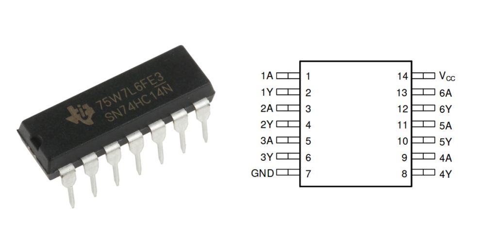
| Pin Number | Pin Name | Description |
|---|---|---|
| 1 | 1A | Inverter 1 Input (Schmitt Trigger Input) |
| 2 | 1Y | Inverter 1 Output |
| 3 | 2A | Inverter 2 Input (Schmitt Trigger Input) |
| 4 | 2Y | Inverter 2 Output |
| 5 | 3A | Inverter 3 Input (Schmitt Trigger Input) |
| 6 | 3Y | Inverter 3 Output |
| 7 | GND | Ground Pin (Negative Supply) |
| 8 | 4Y | Inverter 4 Output |
| 9 | 4A | Inverter 4 Input (Schmitt Trigger Input) |
| 10 | 5Y | Inverter 5 Output |
| 11 | 5A | Inverter 5 Input (Schmitt Trigger Input) |
| 12 | 6Y | Inverter 6 Output |
| 13 | 6A | Inverter 6 Input (Schmitt Trigger Input) |
| 14 | VCC | Positive Supply Voltage (Recommended +5V) |
When you’re working with the SN74HC14N, you’ll have six separate Schmitt-trigger inverters, each with its own input labeled “A” and an output labeled “Y.” It’s essential to power this chip with a steady supply—5 volts DC usually works best. Don’t forget to add a small decoupling capacitor right next to the chip’s power pins to keep noise down and ensure stable operation.
Make sure the ground pin (GND) is solidly connected; a good grounding point prevents unwanted noise from messing up your signals. Another quick tip: any input pins you’re not using should never be left floating. Tie them down to ground or connect them to a stable voltage level. Leaving them disconnected can cause unpredictable behavior or waste battery life.
Following these tips ensures your chip runs smoothly and helps you avoid frustrating issues when testing or building your circuits.
sn74hc14n equivalent schmitt trigger
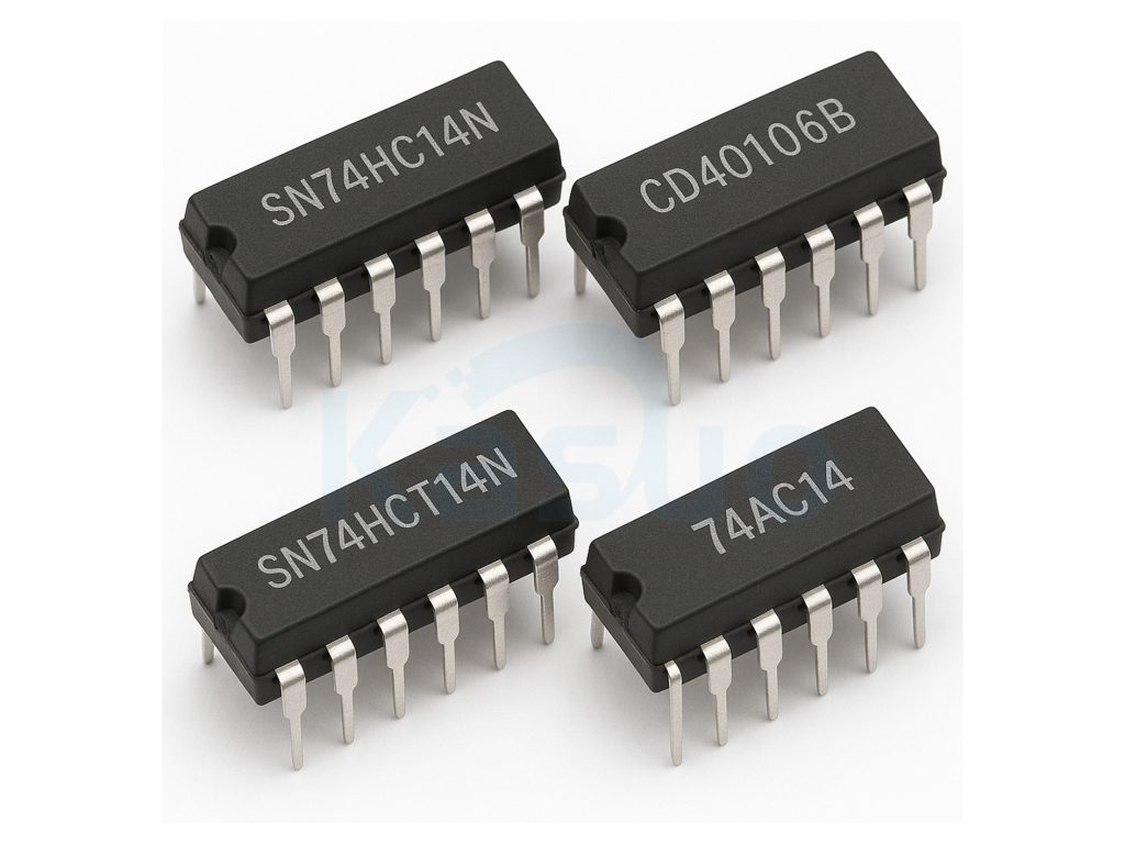
| Parameter | SN74HC14N | CD40106B | SN74HCT14N | 74AC14 |
|---|---|---|---|---|
| Package Type | DIP-14 | DIP-14 | DIP-14 | DIP-14 |
| Supply Voltage Range | 2 ~ 6 V | 3 ~ 15 V | 4.5 ~ 5.5 V | 2 ~ 6 V |
| Propagation Delay (Typical) | 15 ns | 60 ns | 20 ns | 7 ns |
| Input Logic Level | CMOS | CMOS | TTL Compatible | CMOS |
| Operating Temperature Range | -40 ~ 85°C | -55 ~ 125°C | -40 ~ 85°C | -40 ~ 85°C |
| Output Current Capability (Typical) | ±5.2 mA | ±1.5 mA | ±4 mA | ±24 mA |
If you’re considering replacing the SN74HC14N with another chip, here’s some quick advice. The CD40106B can handle a wide voltage range—from about 3 to 15 volts—which makes it perfect if your circuit needs higher voltage flexibility. Just keep in mind, it’s slower and can’t drive as much current, so use it only in lower-speed or less demanding applications.
For mixing with standard TTL circuits, you might prefer the SN74HCT14N, since it easily interfaces with TTL logic. However, the power supply voltage range is narrower, so you’ll have to make sure your voltage stays stable and precise.
If your design demands high speed and strong output drive, check out the 74AC14. It’s fast and powerful, ideal for rapid signal processing and driving heavier loads. But watch out—it draws more power and can introduce extra noise, so be careful with decoupling your power supply.
Always double-check that your substitute matches your voltage range, speed, and drive capability to avoid issues.
sn74hc14n oscillator circuit schematic
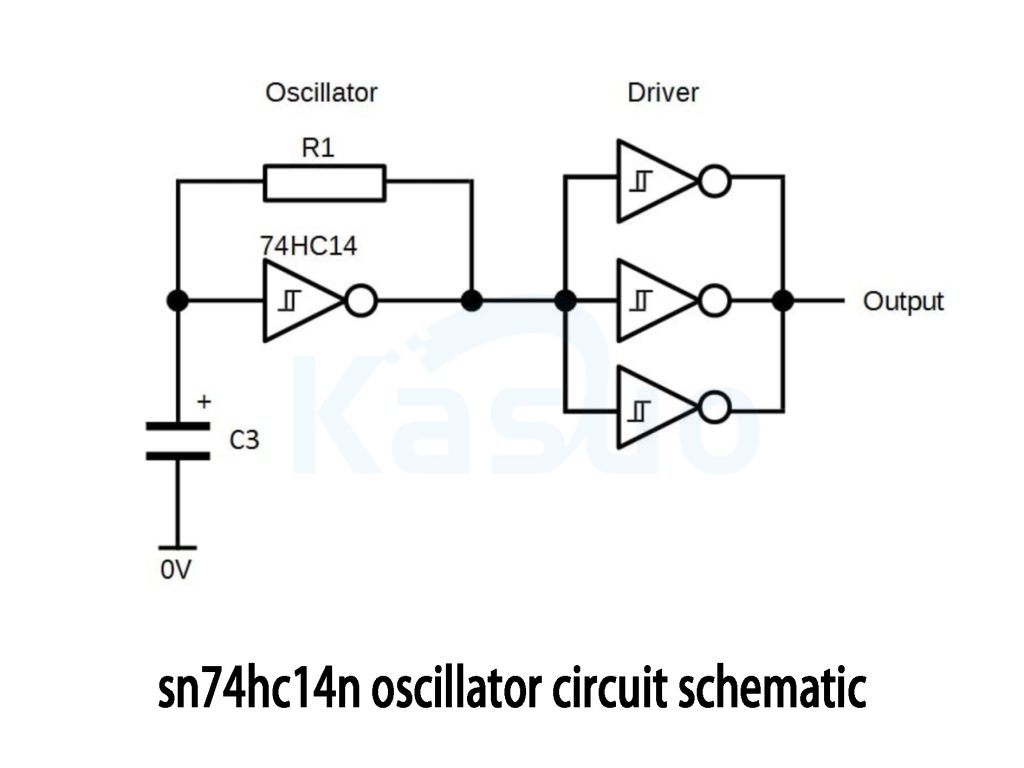
Here’s how you can easily build an oscillator circuit using the SN74HC14N Schmitt-trigger inverter. The setup is simple: just use one inverter from the chip, and connect a resistor (R1) between its input and output pins. Also, put a capacitor (C3) from the inverter input to ground.
When you first power it on, the capacitor charges and discharges repeatedly. Each time the voltage hits the inverter’s switching threshold, the output flips rapidly, giving you a nice clean square wave. To boost this output and handle heavier loads, you can use three additional inverters connected in parallel, giving you a stronger signal suitable for longer cables or bigger loads.
To estimate your oscillator’s frequency, use the simple formula: frequency ≈ 1 / (0.8 × R1 × C3). Pick suitable resistor and capacitor values to match your desired frequency. Always power the circuit with a stable +5V supply, and don’t forget a decoupling capacitor near the chip for smoother operation. Perfect for clocks, signal generators, or LED flashers!
sn74hc14n debounce circuit example
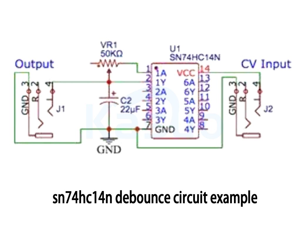
Here’s an easy way you can set up a debounce circuit using the SN74HC14N Schmitt-trigger inverter chip. You’ll need a 50kΩ potentiometer (VR1), a 22µF capacitor (C2), and your input from either a mechanical switch or an external control voltage (CV).
The idea here is pretty straightforward: the potentiometer and capacitor form a simple RC network that smooths out any noise or bouncing from your input signal. The SN74HC14N’s Schmitt-trigger input ensures the output flips cleanly only when the voltage across the capacitor reaches a certain threshold, removing any jitter or instability.
You can tweak the delay and responsiveness by adjusting the potentiometer—larger capacitance or higher resistance means a longer debounce time and a smoother output. This setup is perfect for cleaning up signals from mechanical switches, giving you stable, noise-free digital inputs for microcontrollers, counters, or digital circuits that need reliable logic signals.
sn74hc14n signal conditioning circuit
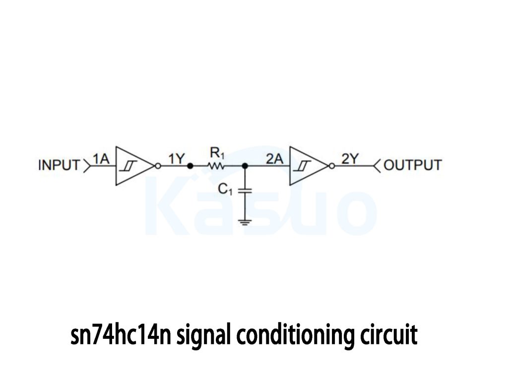
Here’s a straightforward way to clean up noisy or unstable signals using the SN74HC14N chip. You’ll just need two of its Schmitt-trigger inverters along with a simple resistor-capacitor (RC) filter.
First, your input signal goes into the first inverter, which shapes it into a clear square wave. Next, the RC filter (a resistor and capacitor combination) smooths out any spikes, glitches, or unwanted noise, creating a stable, cleaner waveform.
After that, the signal goes through a second inverter, giving you a nicely shaped, reliable digital output ready to use in your circuits.
This setup is perfect if you’re dealing with noisy mechanical switches, relay contacts, or even sensors and encoders that produce jittery digital signals. Using this circuit ensures that your microcontrollers or digital circuits get stable logic signals, eliminating frustrating glitches. It’s simple, effective, and a great trick to have in your electronics toolkit.
sn74hc14n schmitt trigger application guide
The SN74HC14N chip is something you’ll find really handy if you’re into electronics projects. It contains six individual Schmitt-trigger inverters—great for shaping noisy signals, removing interference, and creating clean, stable outputs.
Here’s how it works: Schmitt-trigger inputs have two voltage thresholds. When your input signal crosses the higher threshold, the output quickly flips low; when it drops below the lower threshold, it flips high. This action (known as hysteresis) eliminates unwanted noise and ensures your signals stay stable and reliable.
Common ways you might use it include cleaning up messy input signals, debouncing switches to eliminate jitter, generating square wave oscillators for clocks or timing signals, and converting slow-changing signals into sharp digital logic signals.
A few quick tips for best results: always add a 0.1µF capacitor between the chip’s power and ground to reduce noise. Never leave unused inputs floating—tie them clearly to ground or power. And remember, if you’re driving heavy loads, consider adding extra inverters or a dedicated driver stage.
More Like This

MC5430F
Motorola

JD54LS51BCA
National Semiconductor

USPLSI2032VE-110LB49
Lattice Semiconductor Corporation
74S22PC
Rochester Electronics, LLC

9504DC
National Semiconductor

9005PC
National Semiconductor

9007DC
National Semiconductor
9004DC
National Semiconductor

SN74HC804DWR
Texas Instruments
SN700863DWR
Texas Instruments
4001BDMQB
National Semiconductor
54F02FMQB
National Semiconductor
Also Add to Cart
TC74VHC04FT
Toshiba

MM54HC367E/883
National Semiconductor

XCZU6CG-1FFVB1156I
AMD Xilinx

S-8223CAE-I6T1U
ABLIC Inc.

TP3054WM
Texas Instruments

R3132D14EA-TR-FE
Nisshinbo Micro Devices Inc.

MM74HC165M
Fairchild Semiconductor

S-80138BLPF-JEXTFU
ABLIC Inc.

HA1-2547-9
Harris Corporation

8N3QV01FG-0124CDI8
Renesas Electronics America Inc

XPC850ZT66B
Motorola

ISL6529CB-T
Renesas Electronics America Inc
Related Products
MC5430F
Motorola
JD54LS51BCA
National Semiconductor
USPLSI2032VE-110LB49
Lattice Semiconductor Corporation
74S22PC
Rochester Electronics, LLC
9504DC
National Semiconductor
9005PC
National Semiconductor
9007DC
National Semiconductor
9004DC
National Semiconductor
SN74HC804DWR
Texas Instruments
SN700863DWR
Texas Instruments
4001BDMQB
National Semiconductor
54F02FMQB
National Semiconductor
DM54S20W/883
National Semiconductor

MC3129L
Motorola
4071BDM
National Semiconductor
MC9814P
Motorola
MC9825P
Motorola

74AC11000NS
Texas Instruments
MC5420L
Motorola
MC5401L
Motorola
MC5401F
Motorola
SN74H61N
Texas Instruments
MC5410F
Motorola
MC5430L
Motorola

SN74AS138N-J
Texas Instruments
CD4023BCN
Fairchild Semiconductor
4019BDC
National Semiconductor
74H40DC
National Semiconductor
5420FMQB
National Semiconductor
4025BDM
National Semiconductor
Please send RFQ , we will respond immediately.
