
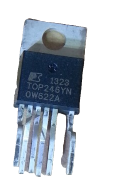
TOP246YN datasheet & circuit diagram | pdf
- Output Isolation: Isolated
- Topology: Flyback
- Fault Protection: Current Limiting, Over Temperature, Over Voltage
- Package: TO-220-7C


FREE delivery for orders over HK$250.00

Quick response, quick quotaton

Flash shipment,no worries after sales

Original channel,guarantee of the authentic products
top246yn circuit diagram| top246yn pinout
TOP246YN Pinout Equivalent


TOP246YN is an offline switching power supply controller. It is characterized by the ability to output a relatively large amount of power, can adapt to a variety of voltages, and the frequency of switching can be selected. It is mainly used in computer power supply, home appliance power supply and other fields.
| Pin Number | Name (Abbreviation) | Description |
|---|---|---|
| 1 | Control (C) | The transistor end of the optocoupler, which receives a feedback signal. |
| 2 | Line Voltage Detection (L) | It is connected to the high voltage DC input with large resistance, and has the function of detection and protection. |
| 3 | External Flow Limit (X) | Connect a resistor to ground and set the maximum current value through the resistor. |
| 4 | Source (S) | A reference point for circuit voltage control. |
| 5 | Frequency (F) | Ground or C-pin, can switch the fast and slow working mode of the power supply. |
| 7 | Drain (D) | Connect the positive side of the power supply to provide the bias current required for start-up to the chip. |
Note: The direct from designation 5 to designation 7 is due to the fact that it is a multifunction pin (M) in other packages, but it is not available in TOP246YN (TO-220-7C).
TOP246YN Same Type Replacement Table
| Picture | Model | Manufacturers | Withstand Voltage Value | Switching Frequency Range | Maximum Duty Cycle | Rated Power | Encapsulation |
|---|---|---|---|---|---|---|---|
 |
TOP246YN | Power Integrations | 700V | 110kHz – 132kHz | 80% | 150W | TO-220 |
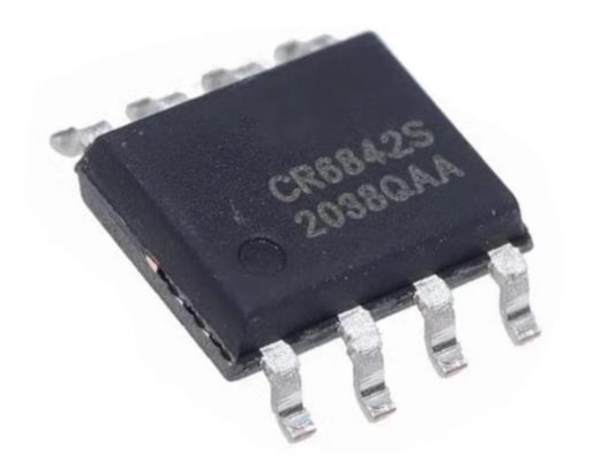 |
CR6842S | NCE Power | 800V | 50kHz – 100kHz | 80% | 50W | SOIC-8 |
 |
ICE3BR2565JF | Infineon Technologies | 650V | 20kHz – 100kHz | 75% | 65W | TO-220 |
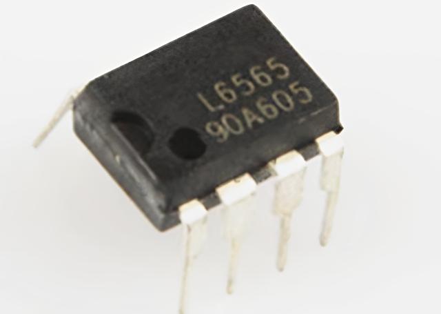 |
L6565 | STMicroelectronics | 700V | 100kHz – 150kHz | 50% | 70W | DIP-8 |
 |
SM7505 | Sanken Electric Co., Ltd. | 600V | 50kHz – 100kHz | 80% | 50W | SOIC-8 |
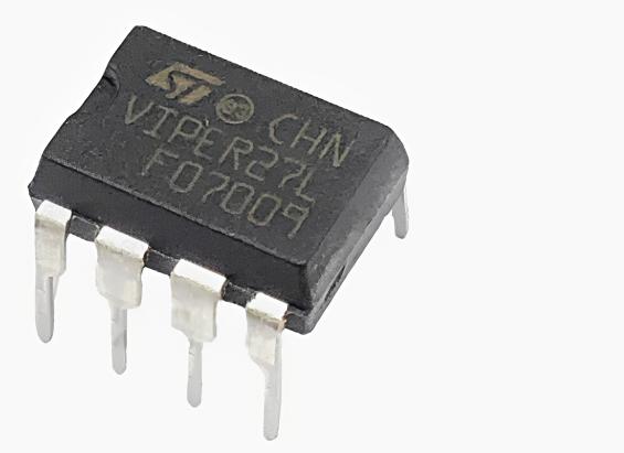 |
VIPer27L | STMicroelectronics | 700V | 50kHz – 100kHz | 80% | 60W | SOIC-8 |
Note: In the same type of replacement table for TOP246YN, CR6842S is the best replacement, with the same withstand voltage value of 700V and a maximum duty cycle of 80%, and although its package form is different, it is no problem to install in most cases. When using CR6842S as a substitute. Note that his power rating of 50W is much lower than TOP246YN’s 150W, and if a higher power is required in the circuit, then he is not suitable. The SM7505, ICE3BR2565JF and VIPer27L have some parameters that are close to the TOP246YN, but the frequency is not the same, and the circuit may need to be adjusted. The maximum duty cycle is different, which will make the output voltage inaccurate, the circuit work chaotic, and the adjustment is difficult to stabilize.
TOP246YN Circuit Diagram
This 30W power supply circuit is designed for high efficiency and compact size, using the TOP244Y (TOPSwitch-GX) IC. It delivers a regulated 12V @ 2.5A output from a wide 85-265VAC universal input, making it ideal for industrial, consumer, and embedded applications.
Key Features and Benefits:
Wide Input Voltage Range (85-265VAC): Compatible with global mains standards.
High Efficiency (up to 80%): Reduced heat generation and improved energy savings.
Precise Current Limit Control: External resistors R1 and R2 optimize the drain current, preventing transformer saturation and reducing component size.
Advanced Protection: Adaptive current limiting reduces overload risks at high-line input. R4 ensures accurate under-voltage (UV) and over-voltage (OV) protection (100 VDC/450 VDC).
Compact Transformer Design: RCD clamp (R3, C3, D1) and high-reflected voltage enable a smaller transformer core and efficient operation.
Extended Duty Cycle (75%): Supports use of a smaller input capacitor (C1), saving board space.
Low Reverse Voltage Stress: Optimized transformer turns ratio allows use of a 60V Schottky rectifier (D8), improving output stage efficiency.
Low Standby Power: Frequency reduction and jitter eliminate the need for dummy loads and enhance EMI compliance (CISPR 22 / FCC Class B).
Output Voltage Regulation:
Regulation is achieved via a low-cost Zener and optocoupler feedback loop. The output voltage is determined by Zener diode VR2, the LED in optocoupler U2, and resistor R6. R8 provides bias for stable operation. This approach ensures ±5% regulation across line and load changes.

More Like This

MC5430F
Motorola

JD54LS51BCA
National Semiconductor

USPLSI2032VE-110LB49
Lattice Semiconductor Corporation
74S22PC
Rochester Electronics, LLC

9504DC
National Semiconductor

9005PC
National Semiconductor

9007DC
National Semiconductor
9004DC
National Semiconductor

SN74HC804DWR
Texas Instruments
SN700863DWR
Texas Instruments
4001BDMQB
National Semiconductor
54F02FMQB
National Semiconductor
Also Add to Cart

71M6523-IM/F
Analog Devices Inc./Maxim Integrated
GAL22V10D-15LPI
Lattice Semiconductor Corporation

LTC4162IUFD-FST#PBF
Analog Devices Inc.
XC9237B1DD0R-G
Torex Semiconductor Ltd

74LVC1G126GM/S500115
NXP USA Inc.

SN74AVCH8T245PWR
Texas Instruments

OMAP3515ECBC
Texas Instruments

MIC24051YJL-TR
Microchip Technology

8N3QV01EG-0026CDI
Renesas Electronics America Inc
XC6136N43B9R-G
Torex Semiconductor Ltd

SN74AS1034ANSRE4
Texas Instruments

LM4040AIM3-2.5
Analog Devices Inc./Maxim Integrated
Related Products
MC5430F
Motorola
JD54LS51BCA
National Semiconductor
USPLSI2032VE-110LB49
Lattice Semiconductor Corporation
74S22PC
Rochester Electronics, LLC
9504DC
National Semiconductor
9005PC
National Semiconductor
9007DC
National Semiconductor
9004DC
National Semiconductor
SN74HC804DWR
Texas Instruments
SN700863DWR
Texas Instruments
4001BDMQB
National Semiconductor
54F02FMQB
National Semiconductor
DM54S20W/883
National Semiconductor

MC3129L
Motorola
4071BDM
National Semiconductor
MC9814P
Motorola
MC9825P
Motorola

74AC11000NS
Texas Instruments
MC5420L
Motorola
MC5401L
Motorola
MC5401F
Motorola
SN74H61N
Texas Instruments
MC5410F
Motorola
MC5430L
Motorola

SN74AS138N-J
Texas Instruments
CD4023BCN
Fairchild Semiconductor
4019BDC
National Semiconductor
74H40DC
National Semiconductor
5420FMQB
National Semiconductor
4025BDM
National Semiconductor
Please send RFQ , we will respond immediately.
