
UA741CP pinout, circuit & datasheet
- Amplifier Type: General Purpose
- Number of Circuits: 1
- Output Type: -
- Package: 8-DIP (0.300, 7.62mm)


FREE delivery for orders over HK$250.00

Quick response, quick quotaton

Flash shipment,no worries after sales

Original channel,guarantee of the authentic products
How to get working UA741CP IC? (2 Solutions!!)
UA741CP
If you’ve done analog circuits, you’ve probably used the UA741CP op-amp. It’s been popular for decades because it’s affordable, reliable, and easy to find. It accepts single (5~30V) or dual (±15V) power supplies, and you can fine-tune offset voltage using two external pins. With about 1MHz bandwidth, it handles most low-frequency signals nicely. Plus, it comes with built-in short-circuit protection, and its DIP-8 package is perfect for breadboard experiments.
UA741CP Pinout
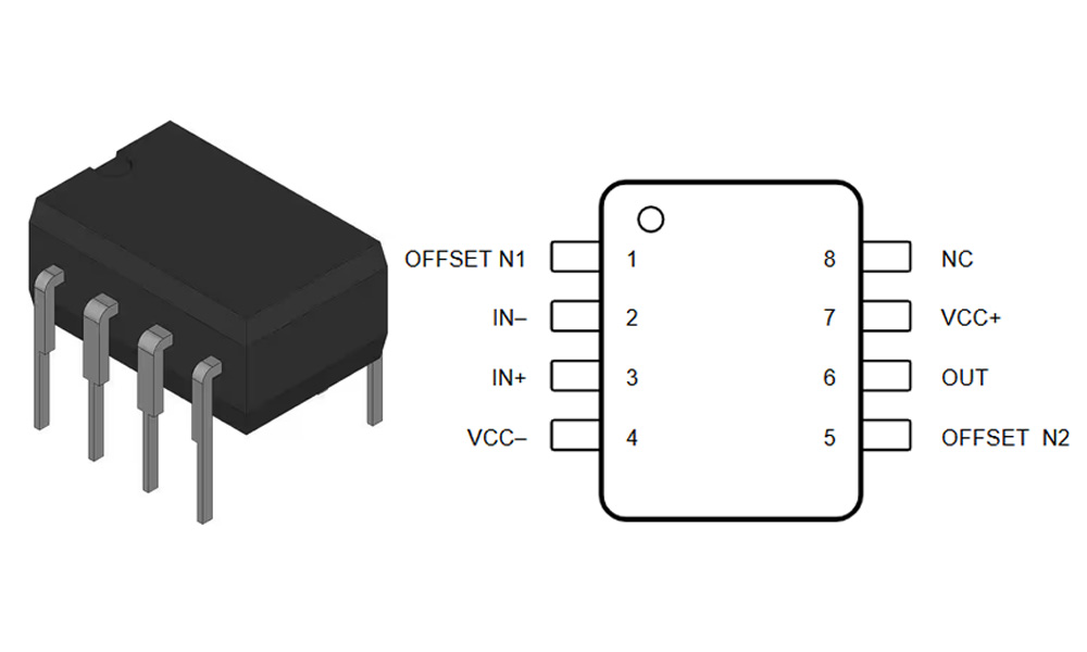
| Pin Number | Name | Function Description |
|---|---|---|
| 1 | Offset Null | Input offset voltage adjustment (used with Pin 5) |
| 2 | Inverting (−) | Inverting input |
| 3 | Non-Inverting (+) | Non-inverting input |
| 4 | V− (VEE) | Negative power supply input or ground |
| 5 | Offset Null | Input offset voltage adjustment (used with Pin 1) |
| 6 | Output | Output terminal |
| 7 | V+ (VCC) | Positive power supply input |
| 8 | NC | No connection (not internally connected) |
When wiring up a UA741CP, pins 2 and 3 handle your differential input signals, and your output comes from pin 6. Pins 4 (-) and 7 (+) connect to your ±12V or ±15V power supplies. Pins 1 and 5 are optional—leave them disconnected if precision isn’t critical, or add a potentiometer if you need offset adjustment. Its DIP-8 package fits neatly into breadboards or PCBs. Just avoid pushing the output too close to the supply rails, as distortion might occur.
UA741CP Equivalent
| Parameter / Model | UA741CP | LM741CN | TL081CP | OP07CP |
|---|---|---|---|---|
| Package | DIP-8 | DIP-8 | DIP-8 | DIP-8 |
| Operating Voltage Range | ±3V ~ ±18V | ±3V ~ ±22V | ±3V ~ ±18V | ±3V ~ ±18V |
| Gain Bandwidth Product (GBW) | 1 MHz | 1 MHz | 3 MHz | 0.6 MHz |
| Typical Slew Rate | 0.5 V/μs | 0.5 V/μs | 13 V/μs | 0.3 V/μs |
| Input Offset Voltage | ≤ 6 mV | ≤ 6 mV | ≤ 3 mV | ≤ 75 μV (more precise) |
| Input Bias Current | 80 nA | 80 nA | 100 pA (lower) | 2 nA |
| Unity Gain Stable | Yes | Yes | Yes | Yes |
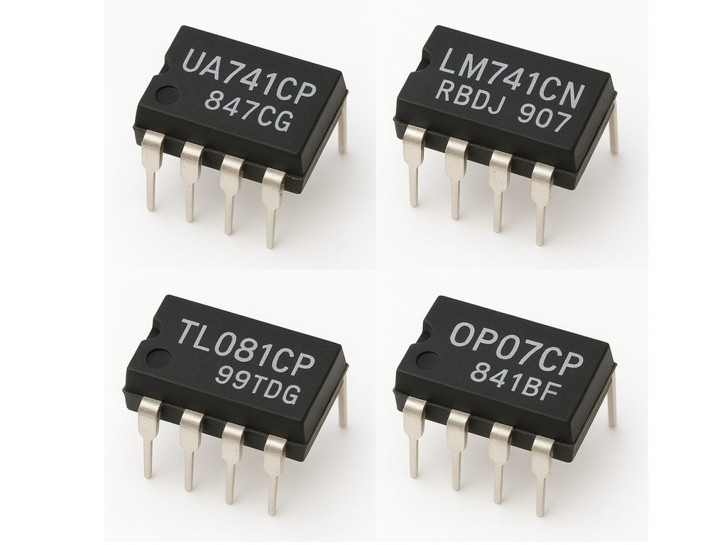
If you can’t find a UA741, the LM741CN is your easiest drop-in replacement—it’s practically identical. The TL081CP is another good choice but with JFET inputs, providing higher speed and lower input current, ideal for faster applications. OP07CP is best if you need low offset voltage for precision circuits, though it’s slower. Always consider slew rate, input current, and bandwidth carefully before swapping chips.
UA741CP Amplifier Circuit Example
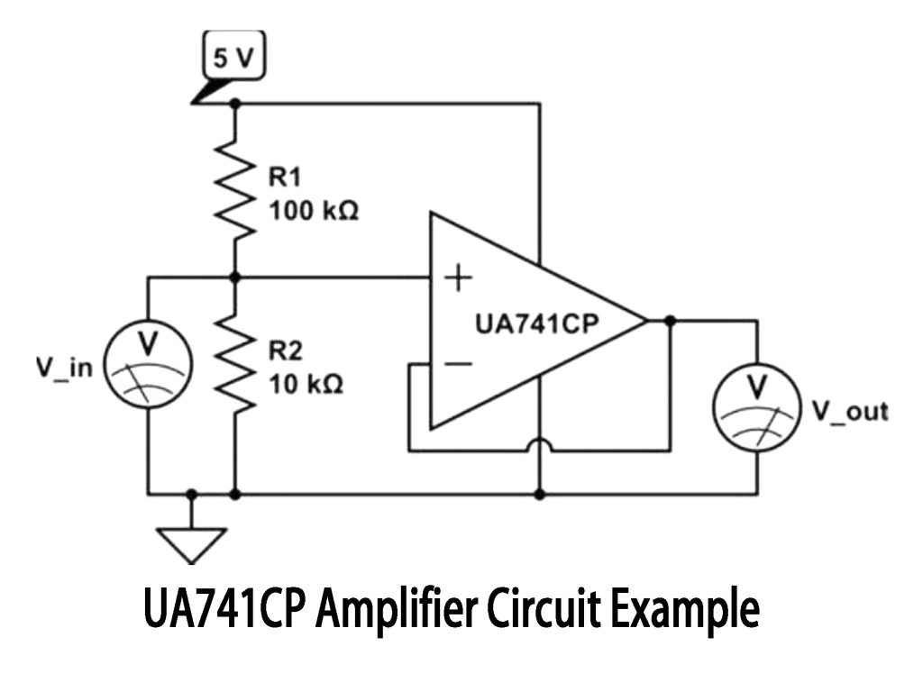
This circuit you see is a simple non-inverting amplifier using UA741CP. Your input signal connects to the positive input of the op-amp, while two resistors (R1 and R2) create negative feedback on the negative input to control gain. With R1=100kΩ and R2=10kΩ, your output gain is about 11 (1+100kΩ/10kΩ). So, an input of 0.2V gives around 2.2V output. Always use ± dual power supply for clean results and avoid distortion.
UA741CP Inverting Amplifier Wiring
When wiring UA741CP as an inverting amplifier, just connect your input signal to the negative input pin through an input resistor (Rin). Use a feedback resistor (Rf) from output back to the negative input, and ground the positive input pin. The gain is simply -Rf/Rin. For instance, Rf=100kΩ, Rin=10kΩ gives you a gain of -10. Remember, use a ±15V dual power supply to achieve proper negative output voltage, ideal for audio or sensor signals.
UA741CP Comparator Circuit Design
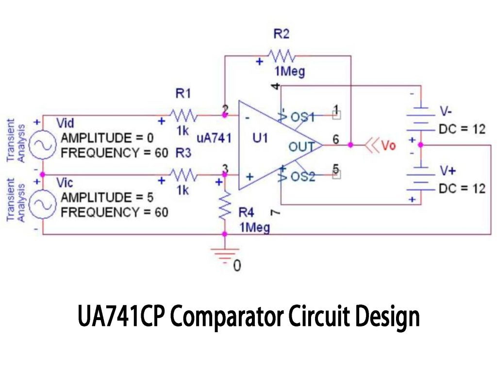
You might think UA741 is just for amplification, but it also works nicely as a basic comparator. In this circuit, your two input voltages connect to the op-amp inputs. When Vic (positive input) exceeds Vid (negative input), the output swings to about +12V; otherwise, it goes down to -12V. Adding resistor R2 provides hysteresis, preventing jitter around the switching point. While UA741 isn’t suitable for high-speed precision comparisons, it’s great for simpler tasks like voltage threshold detection or battery monitoring.
UA741CP Audio Preamp Project
If you’ve got a UA741CP lying around, building an audio preamp for your mic or guitar is straightforward. Just feed your audio signal into the positive input and use two resistors (like 100kΩ and 10kΩ) to set a gain of about 11x. Use coupling capacitors (1~10μF) on input and output to block DC. Power it with ±12V or ±15V for better audio range. For condenser mics, add a simple transistor stage upfront. Need even cleaner sound? Consider upgrading to TL072 or NE5532 op-amps.
More Like This

ZXCW6100S28
Diodes Incorporated

TDA8541T/N1,112
NXP USA Inc.

TDA8541T/N1,118
NXP USA Inc.

TDA7056B/N1,112
NXP USA Inc.
,SOT157-2.JPG "TDA2616Q/N1,112")
TDA2616Q/N1,112
NXP USA Inc.

TDA8547TS/N1,112
NXP USA Inc.
TDA8547TS/N1,118
NXP USA Inc.

NE58633BS,157
NXP USA Inc.
NE58633BS,115
NXP USA Inc.

SA58670BS,115
NXP USA Inc.

TS4961TIQT
STMicroelectronics
,SOT523-1.JPG "TFA9842J/N1,112")
TFA9842J/N1,112
NXP USA Inc.
Also Add to Cart

K4B4G1646E-BYMA0CV
Samsung

RT9297GQW
Richtek USA Inc.
MAX274AEWI+T
Analog Devices Inc./Maxim Integrated

ICS853013AMLFT
Renesas Electronics America Inc

DS80EP100SD/NOPB
Texas Instruments

74ALVC164245PVG
IDT, Integrated Device Technology Inc

CY37256VP160-100AXI
Cypress Semiconductor Corp

NTS0102GU8,125
NXP USA Inc.

MC74AC162DR2
onsemi

LM76202QPWPRQ1
Texas Instruments

LP3982IMM-ADJ/NOPB
Texas Instruments

MAX8862RCSE
Analog Devices Inc./Maxim Integrated
Related Products
ZXCW6100S28
Diodes Incorporated
TDA8541T/N1,112
NXP USA Inc.
TDA8541T/N1,118
NXP USA Inc.
TDA7056B/N1,112
NXP USA Inc.
TDA2616Q/N1,112
NXP USA Inc.
TDA8547TS/N1,112
NXP USA Inc.
TDA8547TS/N1,118
NXP USA Inc.
NE58633BS,157
NXP USA Inc.
NE58633BS,115
NXP USA Inc.
SA58670BS,115
NXP USA Inc.
TS4961TIQT
STMicroelectronics
TFA9842J/N1,112
NXP USA Inc.

SA58632BS,118
NXP USA Inc.

TDA1308TT/N2,118
NXP USA Inc.
TDA8552TS/N1,112
NXP USA Inc.
TDA8552TS/N1,118
NXP USA Inc.
TDA1517/N3,112
NXP USA Inc.
TDA7056A/N2,112
NXP USA Inc.

SA58671UK,027
NXP USA Inc.

TDA8948J/N1,112
NXP USA Inc.
TFA9843AJ/N1,112
NXP USA Inc.

SA58637BS,118
NXP USA Inc.

TDA7052A/N2,112
NXP USA Inc.

TDA8551T/N1,112
NXP USA Inc.

TDA8551T/N1,118
NXP USA Inc.
SA58672UK,027
NXP USA Inc.
SA58670ABS,115
NXP USA Inc.

SA58631TK,157
NXP USA Inc.
SA58631TK,118
NXP USA Inc.
SA58631TK,115
NXP USA Inc.
Please send RFQ , we will respond immediately.
