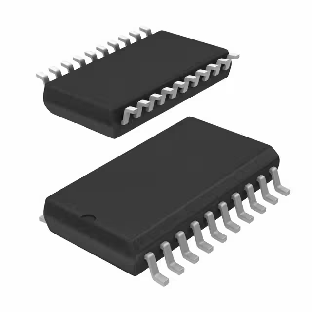
USB2514BI-AEZG datasheet, schematic & TR
- Protocol: USB
- Function: Hub Controller
- Interface: USB
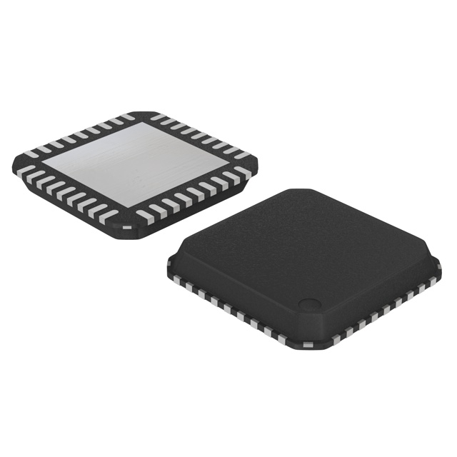
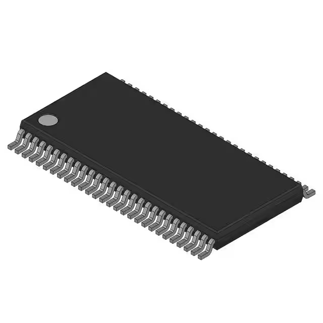
- Package: 36-VFQFN Exposed Pad

FREE delivery for orders over HK$250.00

Quick response, quick quotaton

Flash shipment,no worries after sales

Original channel,guarantee of the authentic products
USB2514BI-AEZG
The USB2514BI-AEZG from Microchip is a solid choice if you’re looking to add extra USB ports to your system. It supports up to four USB 2.0 downstream ports, making it perfect for devices like computers, embedded systems, or any electronics that need more USB connections.
With fast data transfer speeds (full-speed and high-speed), it ensures your devices run smoothly. It also stands out with its low power consumption, which is great for battery-powered applications. Plus, the built-in overcurrent protection keeps your devices safe.
Overall, if you’re looking to boost your system’s USB connectivity without compromising on performance or power efficiency, this hub is a great option.
USB2514BI-AEZG Pinout Diagram

| Pin Number | Pin Name | Description |
|---|---|---|
| 1 | VBUS | USB Power Supply (5V) |
| 2 | GND | Ground |
| 3 | DP1 | USB Data Plus (Port 1) |
| 4 | DM1 | USB Data Minus (Port 1) |
| 5 | DP2 | USB Data Plus (Port 2) |
| 6 | DM2 | USB Data Minus (Port 2) |
| 7 | DP3 | USB Data Plus (Port 3) |
| 8 | DM3 | USB Data Minus (Port 3) |
| 9 | DP4 | USB Data Plus (Port 4) |
| 10 | DM4 | USB Data Minus (Port 4) |
| 11 | SUSPEND | Suspend mode control (active low) |
| 12 | RESET | Reset control for the USB hub |
| 13 | OC1 | Overcurrent detection for Port 1 |
| 14 | OC2 | Overcurrent detection for Port 2 |
| 15 | OC3 | Overcurrent detection for Port 3 |
| 16 | OC4 | Overcurrent detection for Port 4 |
-
VBUS (Pin 1): This is your power source—without it, nothing works. Think of it like the gas pedal in a car; if it’s not connected, you won’t go anywhere.
-
Ground (Pin 2): Like the foundation of a house, this ensures stable operation. If it’s missing, your system can wobble.
-
DP and DM Pins (Pins 3-10): These are your data highways. If routed wrong, it’s like having a bumpy road—data loss or slow speeds.
-
SUSPEND (Pin 11): It’s like sleep mode for your hub. Use it to save power when the hub’s not in use.
-
RESET (Pin 12): Reset it to clear any glitches, like rebooting your phone.
-
OC Pins (Pins 13-16): Think of these as your circuit breakers—protecting your ports from overcurrent.
USB2514BI-AEZG Equivalent USB Hub Controller

| Feature | USB2514BI-AEZG | TUSB2046B | GL850G |
|---|---|---|---|
| Number of Downstream Ports | 4 | 4 | 4 |
| USB Standard | USB 2.0 | USB 2.0 | USB 2.0 |
| Package Type | QFN-32 | TQFP-32 | TQFP-32 |
| Operating Voltage | 4.5V to 5.5V | 4.5V to 5.5V | 4.5V to 5.5V |
| Data Transfer Rate | Full-Speed, High-Speed | Full-Speed, High-Speed | Full-Speed, High-Speed |
| Overcurrent Protection | Yes | Yes | Yes |
| Low Power Mode | Yes | Yes | Yes |
| Temperature Range | -40°C to 85°C | -40°C to 85°C | 0°C to 70°C |
| Package Size | 5mm x 5mm | 7mm x 7mm | 7mm x 7mm |
When considering replacements, here’s what you need to keep in mind:
-
Pin Compatibility: All three controllers offer four USB ports and are in similar packages (TQFP or QFN). But always double-check the pinout to make sure they’ll fit your current design.
-
Operating Conditions: While they all work within a 4.5V to 5.5V range, the GL850G can handle higher temperatures (up to 70°C). If your system needs to work in extremely cold environments, you might want to stick with the USB2514BI-AEZG or TUSB2046B, as they go down to -40°C.
-
Power Management: All of them handle power management well, including low power modes and overcurrent protection, so they won’t mess with your system’s efficiency or safety.
-
Temperature Range: If you’re in a tough environment, the USB2514BI-AEZG or TUSB2046B are a better bet with their wider temperature range.
USB2514BI-AEZG USB Hub Circuit Design
For the USB2514BI-AEZG hub, you’ll need a solid 5V power supply to keep it running smoothly. The VBUS pin connects to this power, and the GND pin goes to your system ground. Then, for the data transfer, each of the four downstream ports has its own pair of data lines (DP and DM). The OC pins for each port are there to protect against overcurrent by shutting down any problematic ports.
You’ll also have the SUSPEND pin to put the hub in a low-power state when it’s not in use, and the RESET pin is there to reset the hub if things go wrong.
Make sure you’ve got decoupling capacitors for clean power, and use good components to handle overcurrent detection. Finally, don’t forget to manage the SUSPEND pin for power efficiency when idle.
USB2514BI-AEZG USB 2.0 Hub Schematic

The Upstream PHY connects to your host’s USB port, handling both the data and power signals. It detects whether the hub gets its power from the USB bus or from an external source.
Power regulation is handled by a 1.2V regulator for internal logic, and a 3.3V supply for the entire hub. The VDDA powers specific analog circuits, while VDDCR ensures the system gets the right voltage levels.
The Repeater boosts the USB signal to downstream ports, and the Serial Interface Engine converts the data into a serial format. The PLL makes sure everything is in sync for smooth data transfer.
USB ports connect devices like keyboards or flash drives, and the port controllers manage communication. LED drivers indicate port status, while routing logic ensures proper data flow. Plus, the OC detection prevents devices from drawing too much current, protecting both the hub and the host.
USB2514BI-AEZG Power Management Circuit
The USB2514BI chip is part of the USB2514 family and acts as the hub controller. It manages the USB data and power lines, letting multiple devices connect to a single USB port.
The Resistor (R_res) is connected to the 3.3V and 5V supply lines. It helps set current limits and stabilizes the signal between components for proper voltage regulation.
The USB Port Power Controller handles power distribution to the connected devices. The IN pin gets power from an upstream source, like a host or power supply. The EN pin controls power to the USB port. The FLAG pin shows the port’s status—whether it’s active, powered, or in error.
PRTPWR and OCS_N are important too. PRTPWR manages the power to the port, and OCS_N signals any overcurrent condition. VBUS is the 5V power line that ensures your devices get stable power.
USB2514BI-AEZG USB Hub PCB Layout Guidelines
For the USB2514BI-AEZG, make sure you place decoupling capacitors near the power pins, especially for the 3.3V and 5V rails. These help filter noise and keep the voltage steady. Use a solid power plane for both voltages to reduce noise and ensure reliable power delivery.
USB signals (D+ and D-) should be routed as matched pairs, keeping the traces as short and parallel as possible. This helps maintain signal quality. For the VBUS line, make it wide enough to handle the current for multiple USB devices. Add current-limiting resistors or fuses for overcurrent protection.
For grounding, a single, continuous ground plane works best. Avoid split planes to prevent noise. Add ESD protection diodes near USB ports and consider using a crystal oscillator with short, direct traces to reduce interference. Proper thermal relief will also help manage heat.





.jpg)

