This schematic shows a simple and effective power design for the AD9361BBCZ SDR transceiver. It uses the ADP5040 PMIC to provide clean 1.8V and 3.3V rails, and an additional ultra-stable 1.3V through the ADP1755 regulator for the chip’s core digital and analog circuits. Perfect if you’re building embedded SDR modules, small base stations, or MIMO systems—clean and stable power is key for top RF performance.

AD9361BBCZ datasheet & price
Explore the AD9361BBCZ Reference Manual for comprehensive details and specifications. Find all the essential information, including pricing, to help you utilize this component effectively in your projects.
- Type: TxRx Only
- RFFamily/Standard: Cellular
- Protocol: LTE
- Package: 144-LFBGA, CSPBGA


FREE delivery for orders over HK$250.00

Quick response, quick quotaton

Flash shipment,no worries after sales

Original channel,guarantee of the authentic products
AD9361BBCZ DataSheet — ingketech.net
AD9361BBCZ
If you’re working on SDR or wireless communication projects, the AD9361BBCZ transceiver is an ideal choice. It covers a wide frequency range (70 MHz to 6 GHz), handling LTE, WiFi, 5G and more. Bandwidth is adjustable (200 kHz–56 MHz), and it integrates mixers, filters, ADCs, and DACs, simplifying your RF design. With support for 2×2 MIMO, high performance, and low power consumption, it’s perfect for portable devices, small base stations, wireless video, radar, and similar applications.
AD9361BBCZ Pinout Diagram
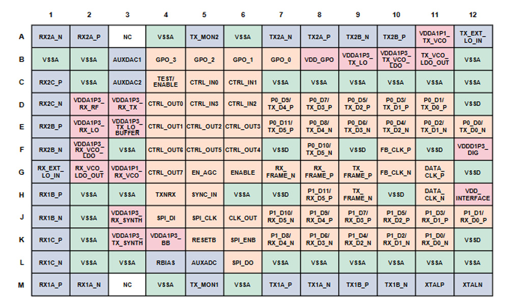
| Pin Type | Typical Pins | Function Description |
|---|---|---|
| Power Supply Pins | VDD_GPO, VDDD (1.3V), VDD_INTERFACE (1.2V–2.5V) | Provide independent power domains for different modules; analog paths and digital I/O powered separately |
| Ground Pins | VSSA (analog ground), VSSD (digital ground) | Separate analog and digital grounds; strict PCB ground plane separation required |
| RF Input/Output Pins | TX2A_P/N, TX2B_P/N, RX2C_P/N, etc. | High-frequency analog transmit/receive paths, supports differential RF signal communication |
| Control Signal Pins | CTRL_IN03, CTRL_OUT07, EN_AGC | Manual gain control, AGC enable, status monitoring, etc. |
| Digital Interface Pins | P0_Dx, P1_Dx, DATA_CLK_P/N | CMOS/LVDS interface, used for data exchange with FPGA or microcontrollers |
| Reset & SPI Pins | RESETB, SPI_ENB | Reset chip and enable SPI interface, used for external configuration control |
When designing with the AD9361BBCZ, separate analog, digital, and IO power rails clearly with proper decoupling. For grounding, route analog and digital grounds separately and join near the chip to reduce interference. RF pins (TX/RX) require accurate 50Ω matching; unused pins can connect to a 1.3V bias voltage. Digital interfaces (CMOS or LVDS) need SPI configuration first. Follow the official reference layout with Rogers PCB materials and impedance control for best RF performance.
AD9361BBCZ Equivalent RF Transceiver
| Parameter / Model | AD9361BBCZ | AD9364BCPZ | ADRV9002 |
|---|---|---|---|
| Package | 144-BGA (10×10 mm) | 144-BGA (10×10 mm) | 15×15 mm multi-BGA |
| RF Coverage Range | 70 MHz – 6.0 GHz | 70 MHz – 6.0 GHz | 30 MHz – 6.0 GHz |
| Channel Configuration | 2×Tx / 2×Rx MIMO | 1×Tx / 1×Rx | 2×Tx / 2×Rx + 2×Rx monitor |
| Channel Bandwidth | 200 kHz – 56 MHz | 200 kHz – 56 MHz | Wider (high-performance ADC/DAC) |
| Noise Figure (NF) | < 2.5 dB | < 2.5 dB | Optimized, high sensitivity (~3 dB) |
| ADC / DAC Resolution | 12-bit, 2 channels each | 12-bit, 1 channel each | 16-bit, high resolution |
| Auto Calibration | Supported | Supported | Supported, more advanced |
| Power Consumption | ~600–700 mW (full load) | Similar | ~1W/channel, higher consumption |
| Target Applications | SDR, base station, wireless test systems | Cost-sensitive, single-channel systems | Defense, 5G, electronic warfare, high-end systems |
If you can’t get the AD9361, consider the AD9364 or ADRV9002. The AD9364 is almost identical but supports single-channel only—no MIMO. It’s cheaper if you don’t need dual channels. For better performance, higher accuracy, and lower distortion, choose ADRV9002, but remember it consumes more power and requires different interfaces and power management. Pay attention to RF layout, impedance matching, and interface changes when switching.
AD9361BBCZ SDR Transceiver Circuit Example

AD9361BBCZ Linux Driver Setup
AD9361BBCZ High Frequency Radio Board
If you’re building an advanced wireless radio board for SDR, 5G, or radar applications, the AD9361BBCZ is perfect. Covering frequencies from 70 MHz to 6 GHz, it handles narrowband and wideband signals with ease. It also supports dual-channel MIMO, great for antenna arrays. Pair it with suitable power management (ADP5040+ADP1755), clock references, and RF matching networks, then connect to an FPGA using SPI/LVDS. ADI’s Linux drivers and tools like libiio make development straightforward.
More Like This

TDA5225HTXUMA1
Infineon Technologies

GNSSLC29D10
5G HUB

NCK2910AHN/00200Y
NXP USA Inc.
TEA6856HN/V102Y
NXP USA Inc.
TEA6856HN/V102K
NXP USA Inc.
TEA6856AHN/V205Y
NXP USA Inc.
TEA6856AHN/V205K
NXP USA Inc.
TEA6853AHN/V205Y
NXP USA Inc.
TEA6853AHN/V205K
NXP USA Inc.
TEA6852AHN/V205Y
NXP USA Inc.
TEA6852AHN/V205K
NXP USA Inc.
TEA6851AHN/V205Y
NXP USA Inc.
Also Add to Cart

ESP32-C3-WROOM-02U-N4
Espressif Systems

MF1SPLUS6011DA4/02
NXP USA Inc.
SM0204HC2MDA
L3 Narda-MITEQ
ARE3436LC1
L3 Narda-MITEQ

MAT10250
MACOM Technology Solutions

AMK-2-13+
Mini-Circuits

BIS005Z
Balluff

SI4766-A20-AMR
Skyworks Solutions Inc.

D3C0810S-5
DiTom Microwave

ATS2012-4DB-T05
Susumu
ATT-451F-09-SMA-02
Cinch Connectivity Solutions Midwest Microwave

Z357PA30-USB-P-NC-N
MMB Networks
Related Products
TDA5225HTXUMA1
Infineon Technologies
GNSSLC29D10
5G HUB
NCK2910AHN/00200Y
NXP USA Inc.
TEA6856HN/V102Y
NXP USA Inc.
TEA6856HN/V102K
NXP USA Inc.
TEA6856AHN/V205Y
NXP USA Inc.
TEA6856AHN/V205K
NXP USA Inc.
TEA6853AHN/V205Y
NXP USA Inc.
TEA6853AHN/V205K
NXP USA Inc.
TEA6852AHN/V205Y
NXP USA Inc.
TEA6852AHN/V205K
NXP USA Inc.
TEA6851AHN/V205Y
NXP USA Inc.

TEA6851AHN/V205K
NXP USA Inc.
TEA6850AHN/V205Y
NXP USA Inc.
TEA6850AHN/V205K
NXP USA Inc.
NCK2910HHN/T1AY
NXP USA Inc.
NCK2910AHN/T1AY
NXP USA Inc.
TEF7094AHN/V205DK
NXP USA Inc.
TEF6694AHN/V205DK
NXP USA Inc.
TEF6688HN/V101,557
NXP USA Inc.
TEF6688HN/V101,518
NXP USA Inc.
TEF6686HN/V101,557
NXP USA Inc.
TEF6686HN/V101,518
NXP USA Inc.
TEF6657HN/V101,557
NXP USA Inc.
TEF6657HN/V101,518
NXP USA Inc.
TEF6638HW/V105/SBK
NXP USA Inc.
TEF6638HW/V105/SAK
NXP USA Inc.
TEF6638HW/V105/S3K
NXP USA Inc.
TEF6635HW/V105/S4K
NXP USA Inc.
TEF6635HW/V105/S3K
NXP USA Inc.
Please send RFQ , we will respond immediately.

Please send RFQ , we will respond immediately.
Copyright © 2024 All Rights Reserved