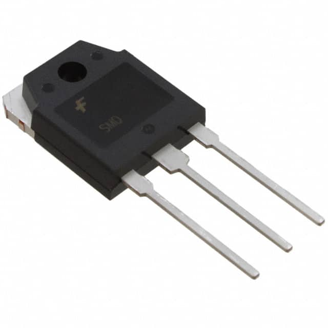
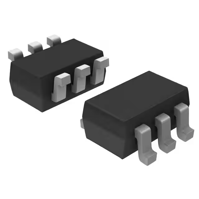
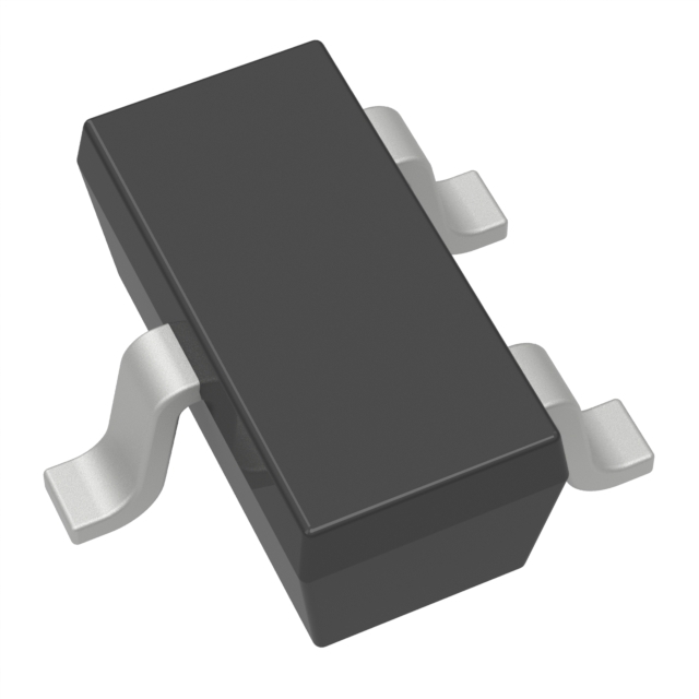
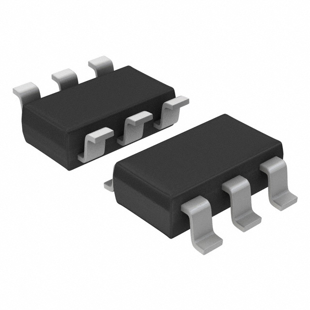
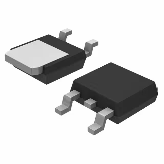
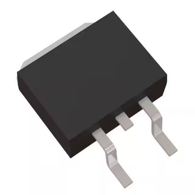
FGA60N65SMD datasheet | IGBT | pdf
- Напряжение коллектор-эмиттер пробой (макс.): 650 В
- Токосъемник (Ic) (макс.): 120 А
- Импульсный коллектор тока (Icm): 180 А
- Упаковка: ТО-3П-3, СК-65-3

БЕСПЛАТНАЯ доставка для заказов свыше HK$250.00

Быстрый ответ, быстрая расценка

Быстрая отправка, никаких проблем после продажи

Оригинальный канал, гарантия подлинности продукции
[SGeC] FGA60N65 Field Stop IGBT 650V-60A
FGA60N65SMD
If you’re looking for a reliable IGBT for high-power projects, the FGA60N65SMD is a great pick. It easily handles currents up to 60A, perfect for powerful applications. Plus, it supports voltages as high as 650V, making it ideal for high-voltage designs. Its low conduction losses mean you’ll waste less energy and keep things efficient. Thanks to its quick switching speed, your circuits run cooler with less power loss. It can even handle short circuits briefly, giving your design extra reliability. Another plus—its positive temperature coefficient helps when paralleling multiple devices. And finally, the robust TO-3P package makes heat dissipation simple, keeping your system stable and reliable.
fga60n65smd pinout

Here’s the pinout table for the FGA60N65SMD IGBT:
| Номер контакта | Имя пин-кода | Описание |
|---|---|---|
| 1 | Ворота (Г) | Gate pin, controls the IGBT switching |
| 2 | Коллекционер (С) | Collector pin, connects to high-voltage load |
| 3 | Эмиттер (Э) | Emitter pin, usually connected to circuit ground |
When you’re using the FGA60N65SMD IGBT, make sure you drive the gate pin correctly—stay within recommended voltages to prevent damage. For the collector pin, connect it carefully to your high-voltage load but don’t exceed its maximum rating of 650V. Also, set up good heat dissipation and include some overvoltage protection. The emitter pin goes directly to ground—make that connection solid to minimize switching noise. Finally, always place insulating thermal material between your IGBT and its heatsink to manage heat effectively. Stick to the guidelines in the datasheet, and you’ll get reliable, long-term performance from your device.
fga60n65smd equivalent igbt


Comparison Table of FGA60N65SMD and Alternative Models:
| Параметр | FGA60N65SMD | FGH60N60SMD | IGW75N65H5 | STGW60H65DRF |
|---|---|---|---|---|
| Производитель | ON Полупроводник | ON Полупроводник | Инфинеон | STMicroelectronics |
| Collector-Emitter Voltage (V) | 650 | 600 | 650 | 650 |
| Continuous Collector Current (A) | 60 | 60 | 75 | 60 |
| Pulsed Collector Current (A) | 180 | 180 | 150 | 120 |
| Gate-Emitter Threshold Voltage (V) | 1.9 | 2.0 | 1.8 | 1.85 |
| Power Dissipation (W) | 600 | 300 | 390 | 390 |
| Тип упаковки | ТО-3П | ТО-247 | ТО-247 | ТО-247 |
| Примечания | Оригинальный номер детали | Lower voltage, ensure compatibility | Higher current, extra cooling required | Similar performance, confirm availability |
When you’re picking an alternative IGBT, always check that its voltage, current, and switching specs match your setup, so you don’t overload your circuit. Pay attention to the packaging—like a TO-247—making sure it fits your PCB and heatsink without hassle. Different IGBTs handle heat differently, so double-check your cooling plan to avoid issues down the line. Also, watch out for switching speeds, since these can affect your efficiency and even cause electromagnetic interference (EMI). Always give the datasheet a close look, ensuring the IGBT fits your application perfectly, so your device runs reliably for years.
fga60n65smd igbt circuit example

This circuit works by using an IGBT switch, like the FGA6DN835MD, to control the flow of current. The DC power source provides power to the IGBT’s collector pin, which allows the switch to operate. A resistor at the collector helps limit the current and protect the circuit. Additionally, inductance is used to reduce high-frequency noise and interference, keeping the system stable. Diodes protect the IGBT from back electromotive force (EMF) that can be generated during switching, preventing damage. Capacitors help stabilize the current flow, especially during switching operations. Lastly, a load resistor ensures that the current doesn’t exceed safe levels, safeguarding the load and the circuit. This setup provides efficient and safe control for various power applications like motor control and voltage regulation.
fga60n65smd inverter wiring diagram

-
Коллекционер (С): Connected to the positive terminal of the DC power source.
-
Эмиттер (Э): Connected to the output terminal and the load.
-
Ворота (Г): Connected to the gate driver circuit for controlling the IGBT switch. It uses a PWM signal to control the gate voltage and, in turn, control the IGBT switch.
fga60n65smd high voltage switching
If you’re working on high-voltage switching projects, the FGA60N65SMD IGBT could be a great choice. It’s built to handle high voltages, making it perfect for power supplies, inverters, and motor control circuits. This device really shines in applications where you need high switching frequencies and low energy losses. It can handle voltages up to 650V, so it’s ideal for switching high-power loads.
The SMD packaging makes it compact and perfect for automated assembly, saving you space and time. Whether you’re in an industrial or automotive setting, this IGBT is designed to perform reliably, ensuring high-efficiency switching. You’ll see it used in things like DC-DC converters, inverters, and UPS systems—anything that needs efficient, reliable power conversion.
fga60n65smd vs igw60n65h5 comparison
Here is a comparison between the FGA60N65SMD and the IGW60N65H5 in tabular format:
| Параметр | FGA60N65SMD | IGW60N65H5 |
|---|---|---|
| Тип | IGBT (Insulated Gate Bipolar Transistor) | IGBT (Insulated Gate Bipolar Transistor) |
| Номинальное напряжение | 650В | 650В |
| Текущий рейтинг | 60А | 60А |
| R_DS(вкл) | 0.75Ω | 0.75Ω |
| Gate Charge (Qg) | 160nC | 150nC |
| Упаковка | SMD (Surface-Mount Device) | TO-247 (Through-hole) |
| Max Operating Temp | 150°С | 150°С |
| Частота переключения | High frequency, efficient for high-speed switching | High frequency, suitable for high-speed switching |
| Приложение | Power supplies, inverters, motor control | Power supplies, industrial motors |
The FGA60N65SMD и IGW60N65H5 IGBTs have similar pinouts but differ in their package types. The Ворота (Г) controls the IGBT’s switching, requiring a driver to ensure proper operation and prevent noise. The Коллекционер (С) handles the current and connects to the positive side of the power circuit, while the Эмиттер (Э) connects to the negative side. The FGA60N65SMD, in a surface-mount package, needs careful PCB layout for heat management, while the IGW60N65H5, with a TO-247 package, is better for higher power applications due to its superior heat dissipation via the mounting tab. Proper grounding and layout are essential for stable operation.
fga60n65smd gate drive circuit

The gate driver (DGDRIVE) is in charge of controlling the gate of the IGBT (in this case, the FGA60N65SMD). When you apply a signal to the gate, it turns the IGBT on, letting current flow from the collector (C) to the emitter (E).
There’s also this resistor (R1) involved, which helps manage how fast the IGBT switches and ensures the current flowing into the gate is kept in check.
Finally, the DC voltage (Vdc) powers the IGBT, giving it the energy it needs to turn on and off according to the gate control signal.
fga60n65smd snubber design example
When using an IGBT like the FGA60N65SMD, a snubber circuit is essential to protect the device from voltage spikes and transients. This circuit typically consists of a resistor and capacitor connected in series across the collector and emitter of the IGBT. The snubber helps absorb excess energy from switching transients, preventing high-voltage spikes that could damage the IGBT. It also limits the rate of voltage change (dV/dt), which reduces the risk of electromagnetic interference and voltage breakdown. The resistor dissipates energy stored in the capacitor, ensuring the IGBT operates reliably and safely in high-power switching applications.
