
ИРФ840 | Datasheet, Circuit Diagram, Equivalent, Pinout STMicroelectronics
- Бренды: STMicroelectronics
- Цена: расследование
- В наличии: 12,612
- Тип полевого транзистора: N-канал
- Напряжение сток-исток (Vdss): 500 В
- Ток непрерывного стока (Id) при 25°C: 8А (Тс)
- Упаковка: ТО-220


БЕСПЛАТНАЯ доставка для заказов свыше HK$250.00

Быстрый ответ, быстрая расценка

Быстрая отправка, никаких проблем после продажи

Оригинальный канал, гарантия подлинности продукции
IRF840 – International Rectifier : Dynamite dv/dt Rating
IRF840 pinout
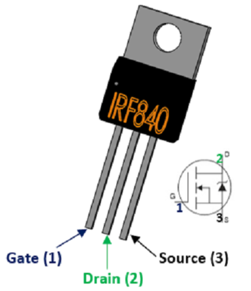
irf840 Picture
| Приколоть | Символ | Описание |
|---|---|---|
| 1 | Ворота | Connect to the control signal port and control the switch through the pin |
| 2 | Осушать | Current flows into the port, connect to the power supply |
| 3 | Источник | Current outflow port, ground |
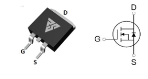
IRF840 Equivalent

irf840 Picture
IRF840 is a high-performance N-channel MOSFET transistor often used in electronic circuit design, widely used in switching power supply circuit, inverter circuit design. Its specific parameters are as follows: the maximum voltage value is 500V, which can meet the requirements of most circuits for voltage; The maximum acceptable current of 8A(with the increase of temperature this value will be reduced to 5.1A) is enough to meet the requirements of most circuits; Continuous high-power work will cause the transistor to heat up and reduce the power of the transistor, so we need to pay special attention to the solution of the heat dissipation problem (such as external heat sink or silicone grease); The on-resistance (Rds(on) of the IRF840 is only 0.7 ohms (rated to a maximum of 0.85 ohms), and the lower on-resistance can effectively reduce additional power losses and improve the efficiency of the circuit. The threshold voltage of IRF840 is 2V~4V, we can easily drive this transistor; And the switching time is only about 400ns, which can be used for high-frequency switching circuits. The package is in the form of TO-220, which has the advantage of easy heat dissipation and easy installation, and the disadvantage is that it takes up relatively large space.
IRF840 Replaceable Chip Table
| Имя | Тип | Вдсс | Вгс | Идентификатор | Пд | Упаковка |
|---|---|---|---|---|---|---|
| STW14NK50Z | N-МОП-транзистор | 500В | 3В | 14A | 150 Вт | ТО-247-3 |
| RS18N50S | N-МОП-транзистор | 500В | 4В | 18А | 140 Вт | ТО-263 |
| SIHG20N50C-JSM | N-МОП-транзистор | 500В | 4В | 18А | 160 Вт | ТО-247 |
| VBM15R08 | N-МОП-транзистор | 500В | 2В | 8А | 170W | ITO-220AB-3 |
| SPW16N50C3 | N-МОП-транзистор | 500В | 3В | 16А | 160 Вт | ТО-247-3 |

STW14NK50Z Picture
RS18N50S Picture

SIHG20N50C-JSM Picture
VBM15R08 Picture

SPW16N50C3 Picture
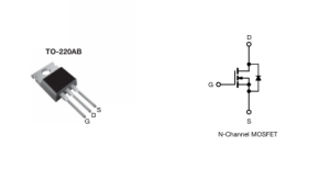
IRF840 Circuit Diagram
Irf840 — это полевая МОП-лампа N-канального типа с корпусом TO-220. Основными характеристиками являются низкий заряд затвора, низкая емкость обратной связи и очень быстрое переключение, поэтому в большинстве случаев она используется в качестве коммутационной трубки, например, в высокоэффективных DC-DC-преобразователях (где различные напряжения постоянного тока могут выводиться путем переключения на разных частотах).
irf840 maximum withstand voltage of 500V, in the series belongs to the highest withstand voltage value of a; large leakage current of 1mA; on-resistance of 0.85Ω (the smaller the on-resistance, indicating that the lower the static power consumption), the on-resistance is the largest in this series, because the irf840 positioning is to be a large withstand voltage and power, so the internal structure of a thicker, on-resistance will be large; Operating temperature range: -55 ℃ ~ +150 ℃; alternative products are: FTK480, KF12N50, IRF740, BSS138, etc. (choose a replacement material to consider the alternative components). Range: -55℃~+150℃; Alternative products are: FTK480, KF12N50, IRF740, BSS138, etc. (When choosing the alternative material, we should consider the voltage withstand value of the alternative components and the maximum current that supports the flow through).
How to drive a mos tube:

irf840 driver circuit diagram
Driving the irf840 requires a large enough transient current, and in addition to direct drive, the more common drive method is push-pull output (totem pole drive). R1 in the figure is the simulated load (can be led, fan, motor and other devices). Since the general microcontroller may not be able to output the current to meet the MOS drive, so we use a PNP and NPN emitter connected (common emitter amplifier circuit), the purpose is to amplify the MOS tube gate drive current.
Больше похожего
~~3.jpg "IRFU9024NPBF")
IRFU9024NPBF
Международный выпрямитель

ФДГ6335Н
онсеми

MMBFJ201
онсеми

IRF3205PBF
Международный выпрямитель

IRFP1405PBF
Международный выпрямитель

IRF3205ZSTRLPBF
Международный выпрямитель

IRFP4229PBF
Международный выпрямитель

IRFB7437PBF
Международный выпрямитель
.jpg "IRLR9343TRPBF")
IRLR9343TRPBF
Международный выпрямитель
IRFP4468PBF
Международный выпрямитель
IRF640NSTRLPBF
Международный выпрямитель

FDS6375
Национальный полупроводник
Также добавить в корзину

NVR5124PLT1G
онсеми
IRFP3206PBF
Технологии Инфинеон

IRLML9301TRPBF
Технологии Инфинеон

2SK3018T106
Ром Полупроводник

IRF7811AVTRPBF
Технологии Инфинеон

FDMC8327L
онсеми
ИРФЗ24НПБФ
Технологии Инфинеон
IRLML6402TRPBF
Технологии Инфинеон
AUIRFS4127TRL
Технологии Инфинеон

АОН7407
Альфа и Омега Полупроводник Инк.

SI4435DY
Фэрчайлд Полупроводник

CSD15571Q2
Техасские инструменты
Сопутствующие товары
IRFU9024NPBF
Международный выпрямитель
ФДГ6335Н
онсеми
MMBFJ201
онсеми
IRF3205PBF
Международный выпрямитель
IRFP1405PBF
Международный выпрямитель
IRF3205ZSTRLPBF
Международный выпрямитель
IRFP4229PBF
Международный выпрямитель
IRFB7437PBF
Международный выпрямитель
IRLR9343TRPBF
Международный выпрямитель
IRFP4468PBF
Международный выпрямитель
IRF640NSTRLPBF
Международный выпрямитель
FDS6375
Национальный полупроводник
IRFB4332PBF
Международный выпрямитель

IRFP3306PBF
Международный выпрямитель

NVTFS5811NLTAG
онсеми
NVTFS4823NTWG
онсеми

NVD5117PLT4G
онсеми
ИРФ200С234
Технологии Инфинеон
.jpg "IRF840PBF")
IRF840PBF
Технологии Инфинеон

АО4407
Альфа и Омега Полупроводник Инк.

2SK3377-Z-E1-AZ
Renesas Electronics America Inc

NVD5867NLT4G
онсеми

NVMFS5A160PLZWFT1G
онсеми

FDWS9510L-F085
онсеми
FDWS9509L-F085
онсеми
NVTFS5826NLWFTAG
онсеми

AON7401L
Альфа и Омега Полупроводник Инк.
АО4407АЛ
Альфа и Омега Полупроводник Инк.

АО3407
Альфа и Омега Полупроводник Инк.

CPH3461-TL-W
онсеми
Пожалуйста, отправьте запрос предложения, мы ответим немедленно.
