A Complete Guide to a Bridge Rectifier: What It Is, Working Principle, and Uses
Author:admin Date: 2025-07-01 09:18 Views:289
What is a Bridge Rectifier?
一個 bridge rectifier is a type of electronic circuit vital for converting alternating current (AC) into direct current (DC). It performs its function by utilizing four diodes arranged in a specific configuration to rectify the positive and negative halves of an AC waveform. The result is a pulsating DC output.
This type of rectifier is common in power supplies that convert standard AC voltage into usable DC voltage for various electronic devices.
Key Components of a Bridge Rectifier
無論是 full bridge rectifier 或 half-bridge rectifier, both will have similar components that make them perform their job. Here are the main components to expect in a bridge rectifier circuit diagram.
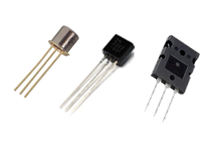
Diodes
There are four diodes at the core. These diodes are arranged in a way that during each half-cycle of the AC input, two diodes conduct the current, while the other two diodes are reverse-biased.
For example, you can have D1 and D3 conducting the positive half-cycle while D2 and D4 are reverse-biased for the negative half-cycle.
AC Power Source
This is the AC input signal that needs rectifying. In this case, it provides the alternating current that the bridge rectifier has to convert to direct current.
Load Resistor (RL)
This is the resistor connected to the output of the bridge rectifier. It is used to represent the load that the output DC voltage would power. This is also where you measure the DC voltage.
Filter Capacitor
This is an optional component. You would use it in parallel with the load resistor for smoothing the pulsating DC output. The result is reduced ripple and improved quality for the output DC voltage.
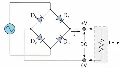
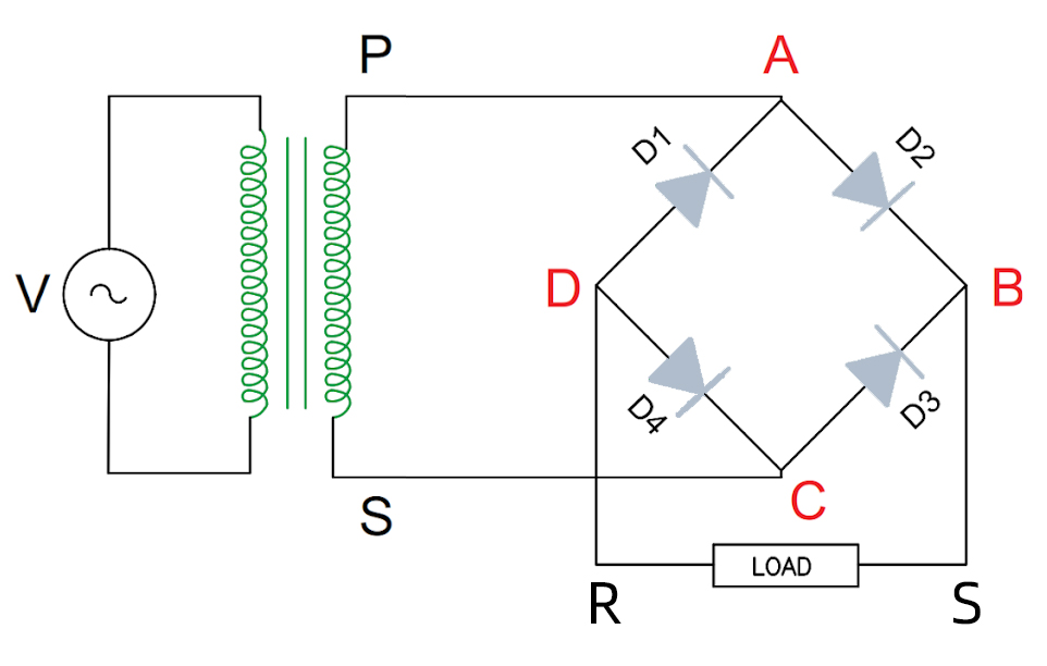
Bridge Rectifier Circuit Diagram
By now, you know how many diodes are used in a bridge rectifier. The bridge rectifier circuit diagram below should help you visualize how it works better.
How Does a Bridge Rectifier Work?
We had mentioned briefly how the full wave bridge rectifier works above, but now we look into more details.
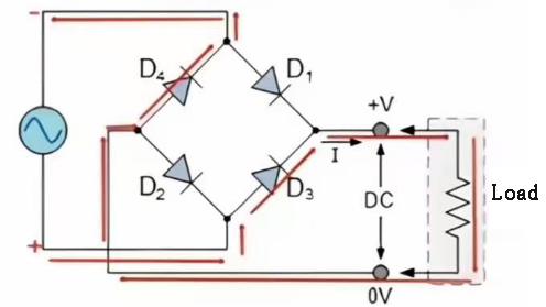
First, we have the diodes and the AC input, which are key in the operation of the diode bridge rectifier. The four diodes are connected in a diamond shape. You have two input terminals for receiving the AC voltage and two output terminals that provide the rectified DC voltage.
During the positive half-cycle of the bridge rectifier circuit, the two diodes are forward-biased, meaning they conduct, while the other two diodes are reverse-biased. Current will flow through the load in one direction.
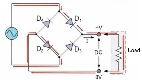
Current flow in a bridge rectifier during the positive half-cycle
As for the negative half-cycle, the diodes in the full diode bridge rectifier that were reverse-biased will now conduct, and the previously conducting diodes will be reverse-biased. The current will still go through the load in the same direction, just as it did during the positive half-cycle.
Since the full bridge rectifiers work by converting both the positive and negative half-cycles of the AC voltage, the resultant is a pulsating DC voltage. Filtering is applied to the DC output by using a capacitor to make it smoother.
Current flow in a bridge rectifier during the negative half-cycle
The work of the capacitor is to charge during the peak of the pulsating DC voltage and discharge during the troughs. This reduces the ripple, creating a more stable DC voltage.
Types of Bridge Rectifiers
Full bridge diode rectifiers works quite well with a wide range of applications. However, there are different types of bridge rectifiers that make this possible. Below are the main types of bridge rectifiers.
Single-phase Bridge Rectifier
This is the most common type in the market. Its job is to convert the alternating current to direct current by using four diodes connected in a bridge configuration. Such a configuration will effectively rectify both the positive and negative half cycles of the AC input. The result is a pulsating DC output.
It is common to find a capacitor being used to filter and smooth the pulsating DC output voltage, thus making it more usable.
This type of bridge rectifier is common in power supplies.
Three-phase Bridge Rectifier
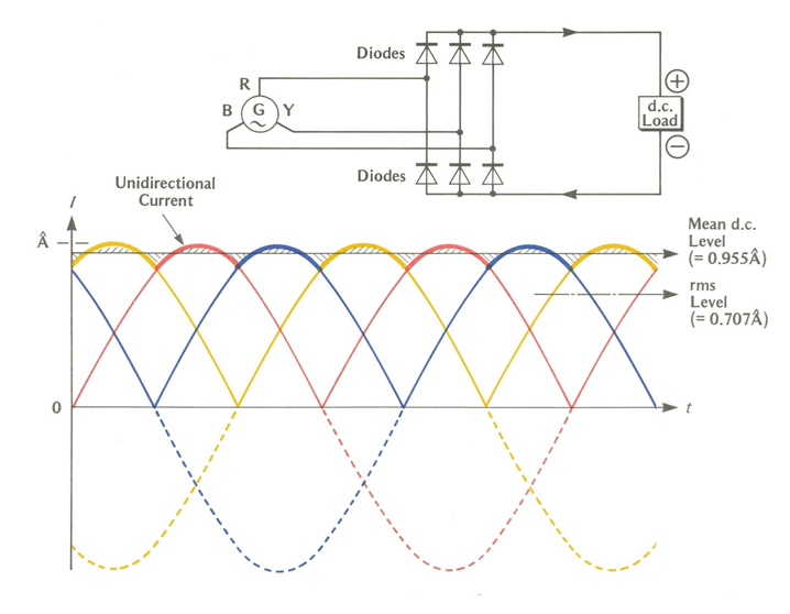
When you look at the bridge rectifier circuit diagram of this unit, you will notice it has six diodes. This is because it is used for converting the three-phase AC power to DC power, compared to the other option above, which works with single-phase AC power.
這 three-phase bridge rectifier is a popular choice for applications that need higher power and smoother DC output compared to when you are working with single-phase rectifiers.
The six diodes are arranged in a bridge configuration so that each phase of the AC input is connected to two diodes.
The biggest advantage is the capability to handle higher power. They also end up with an output voltage with a lower ripple factor. This is expected because of the six-diode configuration.
As for applications, you can expect to encounter them in industrial power supplies, high-power applications, and other related fields.
Uncontrolled Bridge Rectifier
Such a bridge diode rectifier is also used to convert alternating current to direct current using diodes, but this time, they are unidirectional. This means they can only allow current flow in one direction.
This type of rectifier uses a bridge configuration to achieve full-wave rectification. An uncontrolled rectifier is used in applications where a fixed DC voltage is needed. For this reason, it is a key component in many power supplies.
Controlled Bridge Rectifier
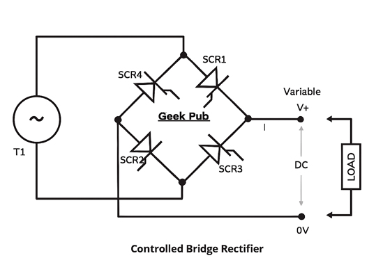
In the case of controlled bridge rectifiers, semiconductor switches such as thyristors and MOSFETs are used to control the output voltage. Unlike uncontrolled rectifiers, which offer a fixed DC output, controlled rectifiers allow the user to adjust the DC output according to the device’s requirements.
This is where you will come across the half- and full-bridge diode rectifiers. The half-controlled rectifiers use a combination of thyristors and diodes to ensure control over only one polarity of the output voltage.
As for the fully controlled bridge rectifiers, they use only thyristors or MOSFETs to control both the polarity and magnitude of the output voltage.
Because you can adjust the DC output in the bridge rectifier, you should find them suitable for motor speed control and power supplies where variable voltage might be necessary.
Applications of Bridge Rectifiers
We have already looked at a couple of applications of the bridge rectifier. Below are some additional options available with this configuration.
- They are important components of power supplies in electronic devices
- They are used in battery chargers for converting AC to DC charging
- Bridge rectifiers can also be used in motor drives to provide the necessary DC power needed to power the DC motors.
- Welding equipment can also use such when DC power is needed for welding processes
- You can expect to find bridge rectifiers in various appliances throughout your house. This includes washing machines, air conditioners, and more.
- Audio amplifiers could also use bridge rectifiers to provide stable DC power needed for amplifying audio signals.
It is easy to see how you can find use for bridge rectifiers so long as there is a need to convert AC voltage to DC voltage.
Pros and Cons of Bridge Rectifiers
Pros
- With a bridge rectifier diode setup, you get a simpler transformer design, which is also cheaper
- Expect to get a high efficiency when working with bridge rectifiers
- There is a higher average output voltage for most applications
- There is a reduced ripple factor, which leads to a smoother DC output
- We find the bridge rectifiers highly reliable
Cons
- There can be an increased voltage drop for each cycle
- There can be increased complexity in design depending on the application
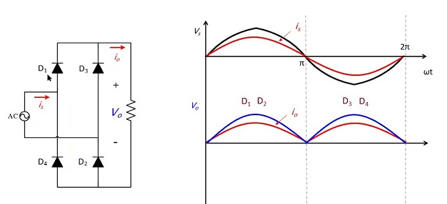
Analysis of a Bridge Rectifier Output Waveform
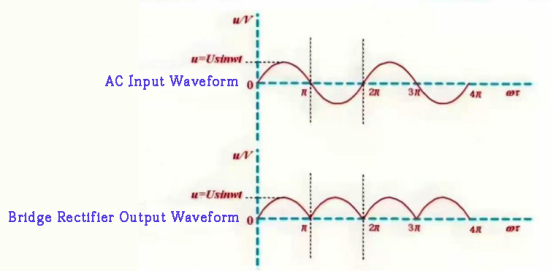
現在你知道了 what do bridge rectifiers do, it is time to do a quick analysis of the output waveform.
The output waveform will have key characteristics to keep in mind. They include:
- Pulsating DC: The output voltage will not be a constant DC voltage, but a series of positive voltage pulses leading to the pulsating DC voltage.
- Ripples: These are AC components found in the output voltage. Having a low ripple factor is more desirable to get a smoother DC output.
- Frequency: The frequency of the output voltage is twice the input AC voltage frequency
- Peak voltage: The peak voltage of the output waveform is lower than the peak voltage of the input AC voltage. This is because there is a voltage drop across the diodes.
- Ripple factor: This is the measure of the ripples or AC components in a rectified output.
For a better analysis of the waveform, you need to use an oscilloscope to check the voltage variations with time.
Look at the ripple and note the amplitude and frequency of these ripples. Measure the DC voltage level and use these measured values to calculate the ripple factor.
Compare this waveform with another waveform when a capacitor is applied to the circuit to fiterl the ripples. You should have a smoother output waveform when a capacitor is used.
Common Bridge Rectifier Issues and Troubleshooting
Sometimes, there can be issues that require testing a bridge rectifier to understand the problem and take steps to rectify it. Below are some of the common issues.
Blown Diodes
You can get one or more diodes in the bridge rectifier failing, which now affects how it works. They can fail because of overcurrent, voltage spikes, and sometimes exceeding their thermal limits.
Under-performing Rectification
The diodes might not always fail, but sometimes they operate suboptimally. This leads to reduced or inconsistent DC output. Also, increased ripple and low voltage.
Excessive Heat
Whether it is a full-wave or half-wave bridge rectifier, it is important for it to work within a specific temperature range. When it is too hot to touch, then you should know there is a problem with the circuit. Most of the time it is a shorted diode or excessive current.
Input Voltage Issues
Having incorrect AC input voltage may lead to damage of the rectifier or sometimes prevent it from functioning correctly.
Intermittent Operation
You can also experience inconsistent or fluctuating output due to loose connections, thermal issues, and failing diodes.
How to Check Bridge Rectifiers
Now that you know more about the common issues, how do you check the bridge rectifier? Here is the process.
- Disconnect power to the circuit before inspecting or testing it.
- Start with a visual inspection to see if there are any signs of cracks or burn marks
- Check the input voltage to make sure it is within the correct range
- Test the diodes with a multimeter so that you can see if they are still working or if they are shorted.
- Test the output voltage to see if it is the expected value. If the voltage keeps fluctuating or it is too low, then it indicates there could be a problem.
- Measure the ripple by using an oscilloscope. You do not want an excessive ripple. This means there is a problem with the circuit.
- Always check all the connections in the circuit, ensuring they are secure.
結論
A bridge rectifier remains an important circuit in electronics. Because of how it works, it can be helpful in various applications especially in power supplies. It helps with getting a stable DC output voltage from an AC input voltage, depending on the configuration. Be sure to look out for signs of damage so that you can troubleshoot and repair the bridge rectifier more easily.
請發送 RFQ,我們將立即回覆。
常見問題
Why are four diodes needed to operate a bridge rectifier?
Four diodes are necessary to ensure that the current flowing in the load is in the same direction regardless of whether it is the negative or positive half of the AC cycle.
What is the output waveform for a bridge rectifier?
The expected waveform will be a pulsating DC waveform. This includes both the positive and inverted negative halves of the AC voltage. This results in a waveform that does not go to negative.
What will happen if one diode fails in a bridge rectifier?
When a single diode fails, the circuit will not work optimally. This is because it might lose one half of the AC voltage, resulting in partial rectification.