2N6027 circuits, datasheet & equivalent
- 品牌: 固態公司
- 下載: -
- 價格: 詢問
- 有存貨: 20,766
- 電流-關閉狀態(最大值): -
- 電流-非重複突波5060Hz(Itsm): -
- SCR類型: -
- 包裹: 盒子

訂單滿 HK$250.00 即可享有免運

快速回應,快速報價

閃電出貨,售後無憂

原廠通路,正品保證
Key Features of the 2N6027 TRIAC
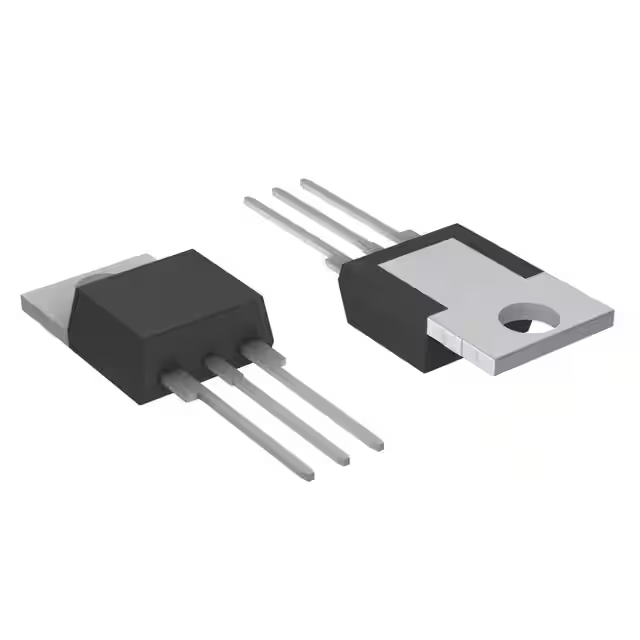
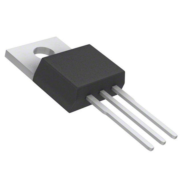
這 2N6027 is a versatile, high-performance TRIAC designed for switching and control applications in AC circuits. It’s capable of handling up to 800V of reverse voltage and 8A of current, making it ideal for medium-power applications such as light dimming, motor speed control, and solid-state relays. The 2N6027 offers low on-state voltage drop, ensuring efficient operation, and features fast switching times, making it suitable for high-frequency AC applications. It’s housed in a TO-220 package, making it easy to integrate into various designs. Whether you’re working on home automation systems or industrial motor control, the 2N6027 provides reliable, efficient switching for AC loads.
2N6027 Pinout
| 別針 | Label | 描述 |
|---|---|---|
| 1 | Anode (A) | The anode pin connects to the positive side of the AC load. |
| 2 | Gate (G) | The gate pin controls the triggering of the TRIAC, turning it on or off. |
| 3 | Cathode (K) | The cathode pin connects to the negative side of the AC load or ground. |
Using the 2N6027 Pinout
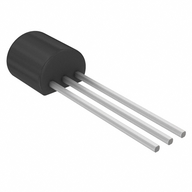
這 2N6027 TRIAC has three key pins: Anode (A), Gate (G), 和 Cathode (K)。 這 Anode (Pin 1) is connected to the positive side of the AC load, while the Cathode (Pin 3) is connected to the negative side or ground. The 門 (Pin 2) controls the switching of the TRIAC; applying a small voltage to the gate will turn the TRIAC on, allowing current to flow from the anode to the cathode. Properly managing the gate voltage is essential for controlling when the TRIAC conducts. Ensure the gate trigger voltage is within specified limits to avoid damage, and remember that the TRIAC is designed for AC control, so it should only be used in alternating current applications.
2N6027 Equivalent Models
Here’s a comparison of equivalent TRIACs with similar packaging and features:
| 模型 | Voltage Rating | Current Rating | Gate Trigger Voltage | 封裝類型 | Key Features |
|---|---|---|---|---|---|
| 2N6027 | 800V | 8A | 1.5V – 3V | TO-220 | Medium power TRIAC, fast switching, low on-state voltage drop |
| BTA10-800V | 800V | 10A | 1.5V – 2.5V | TO-220 | Higher current capacity, similar gate trigger voltage |
| TIC206 | 600伏 | 6A | 1.5V – 3V | TO-220 | Lower voltage rating, fast switching, compact design |
| Q6010L | 600伏 | 10A | 1.5V – 3V | TO-220 | High current rating, low power loss |
Substitution Tips
When replacing the 2N6027, pay attention to key factors such as voltage rating, current rating, 和 gate trigger voltage。 這 BTA10-800V offers a higher current capacity (10A) but retains similar voltage ratings and gate trigger characteristics, making it a good upgrade for high-current applications. If your design can tolerate a lower voltage, the TIC206 offers a smaller footprint and is a good alternative with fast switching times. The Q6010L also provides higher current handling (10A) and is a solid alternative for power applications, but it has a slightly lower voltage rating than the 2N6027. Always ensure that the package type matches your design to avoid compatibility issues.
2N6027 Application
這 2N6027 TRIAC is widely used in applications that involve controlling AC power. It’s perfect for switching devices like light dimmers, motor speed controllers, and solid-state relays. The TRIAC’s ability to switch AC loads with precision makes it ideal for controlling the power to various home appliances, lighting systems, and industrial equipment. It’s also used in heating systems where precise temperature control is required.
2N6027 Testing
Testing the 2N6027 involves checking its ability to trigger and conduct current. To test, you’ll apply a small voltage to the gate pin and monitor if current flows from the anode to the cathode. A multimeter can be used to check the voltage drop across the TRIAC when it’s triggered. Additionally, checking for proper gate trigger voltage and ensuring no shorts or damage to the device during switching cycles is crucial for reliable operation.
2N6027 as a Switch
這 2N6027 works effectively as a switch in AC circuits, turning the power on or off by triggering the gate. When a small current is applied to the gate, the TRIAC becomes conductive, allowing current to flow between the anode and cathode. It can handle high-voltage AC loads and is typically used to switch devices like lamps, motors, and small appliances. Its fast switching characteristics make it ideal for applications where you need efficient and reliable control of AC power.
2N6027 Circuit Diagram and Analysis
這 2N6027 is a programmable unijunction transistor (PUT) commonly used in timing, oscillator, and triggering circuits. Due to its unique characteristics, it requires specific circuit configurations for optimal performance.
Typical Application Circuit
In a basic circuit, the 2N6027 can be configured with two external resistors (R1 and R2) to set its intrinsic standoff ratio (η), valley current (Iv), and peak current (Ip). A capacitor (C) is often used to shape the timing characteristics. The anode (A), gate (G), and cathode (K) pins are connected as follows:
-
Anode (A): Connected to the positive supply voltage.
-
Gate (G): Connected to the junction of R1 and R2.
-
Cathode (K): Connected to the ground or negative side of the circuit.
This configuration allows the 2N6027 to function as a relaxation oscillator, generating pulses at a frequency determined by the values of R1, R2, and C.
Circuit Analysis
-
Triggering: The gate voltage controls the triggering of the PUT. When the anode voltage reaches a certain threshold, the PUT turns on, allowing current to flow from the anode to the cathode.
-
Oscillation: The capacitor charges and discharges through the resistors, creating a timing cycle. The PUT’s negative resistance characteristic causes it to turn off once the voltage drops below a certain level, initiating the next cycle.
-
Adjustability: By varying the values of R1, R2, and C, the oscillation frequency and pulse width can be adjusted to meet specific application requirements.
This circuit configuration is widely used in applications such as tone generators, pulse width modulation, and timing circuits.
For a visual demonstration and step-by-step guide on building and testing a 2N6027 circuit, you can refer to the following video:
,TO-226_straightlead.jpg)



.jpg)
