
4N35 Chip & Pinout | ic circuit diagram Everlight Electronics Co Ltd
- 輸入類型: 直流
- 輸出類型: Transistor with Base
- 電壓 - 輸出(最大): 80伏
- 包裹: 6-DIP(0.300英寸,7.62毫米)


訂單滿 HK$250.00 即可享有免運

快速回應,快速報價

閃電出貨,售後無憂

原廠通路,正品保證
4N35 Optocoupler Complete Details | Working Principle and Best 5 Equivalent Optocouplers
4N35 Optocoupler
The 4N35 is a commonly used optocoupler with a six-pin package, widely applied in circuits requiring electrical isolation. It transmits signals through an internal LED and phototransistor. The LED emits light at the input side, and the phototransistor receives the light and converts it into an electrical signal at the output side, effectively isolating high and low voltage signals. This device is primarily used in microcontroller circuits, power supplies, and other systems that require signal isolation.
4N35 Pinout

| 密碼 | 引腳名稱 | 描述 |
| 1 | Anode (A) | The anode of the LED inside the optocoupler, connected to the input side. |
| 2 | Cathode (K) | The cathode of the LED inside the optocoupler, connected to the input side. |
| 3 | NC | No Connection, usually left floating or not connected. |
| 4 | 發射器(E) | The emitter of the phototransistor, connected to the output side. |
| 5 | 收集器(C) | The collector of the phototransistor, connected to the output side. |
| 6 | 基座(B) | The base of the phototransistor, typically used for controlling current. |
4N35 Equivalent
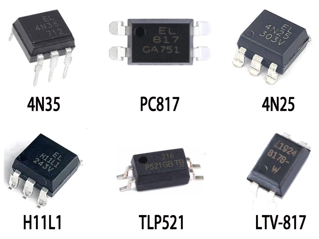
| 範圍 | 4N35 | PC817 | 4N25 | H11L1 | TLP521 | LTV-817 |
| 封裝類型 | 6-Pin DIP | 4-Pin DIP | 4-Pin DIP | 4-Pin DIP | 4-Pin DIP | 4-Pin DIP |
| Input Forward Voltage (V) | 1.2 V | 1.2 V | 1.2 V | 1.2 V | 1.2 V | 1.2 V |
| Input Forward Current (mA) | 10毫安 | 20毫安 | 20毫安 | 20毫安 | 20毫安 | 20毫安 |
| Current Transfer Ratio (CTR) | 50%-600% | 50%-600% | 50%-600% | 50%-600% | 50%-600% | 50%-600% |
| Output Saturation Voltage (V) | 0.4 V | 0.4 V | 0.4 V | 0.4 V | 0.4 V | 0.4 V |
| Operating Temperature (°C) | -55 to 100°C | -55 to 100°C | -55 to 100°C | -55 to 100°C | -55 to 100°C | -55 to 100°C |
| Isolation Voltage (V) | 5,000 V | 5,000 V | 5,000 V | 5,000 V | 5,000 V | 5,000 V |
4N35 Optocoupler Circuit Design

Circuit Working Principle:
Input Side (Arduino Uno R3):
An Arduino digital output pin connects through a 1kΩ resistor to the input LED anode (pin 1) of the 4N35 optocoupler, with the cathode (pin 2) connected to Arduino GND.
When the Arduino outputs a high signal, current flows through the resistor into the internal LED of the 4N35, causing it to emit infrared light.
Output Side (4N35 Phototransistor):
The emitted infrared light activates the internal phototransistor of the 4N35, causing it to conduct.Once the phototransistor conducts, a closed circuit is created from Arduino’s 5V supply through the external LED and the 220Ω resistor, then through the 4N35 phototransistor to GND, lighting up the external LED.
4N35 Alternative to PC817 Optocoupler
Here is a clear side-by-side comparison table highlighting the key differences between the 4N35 和 PC817 optocouplers:
| Parameter / Feature | 4N35 | PC817 |
| Internal Structure | LED + Phototransistor (with base pin available) | LED + Phototransistor (no base pin) |
| Pin Count | 6 pins | 4 pins |
| CTR (Current Transfer Ratio) | 100% typically (at IF = 10mA, VCE=10V) | 50% – 600% (at IF=5mA, VCE=5V) |
| Maximum Collector-Emitter Voltage (VCEO) | 80伏 | 80伏 |
| Isolation Voltage | 5000 Vrms | 5000 Vrms |
| Rise Time (typical) | ~3 µs | ~18 µs |
| Packaging | DIP-6 | DIP-4 |
| Base Connection Availability | Yes (pin 6) | 不 |
| 常見應用 | General isolation, feedback in power supplies, control circuits requiring base connection for transistor | General isolation, feedback loops, signal transfer, common transistor-isolated applications |
how to use 4n35 optocoupler
Simply put, using a 4N35 optocoupler involves lighting its internal LED to activate the internal phototransistor, providing electrical isolation between input and output circuits.
更多類似商品
也加入購物車

HCPL-181-00CE
博通有限公司

6N137-X007T
Vishay 半導體光電部門


PC400J00000F
夏普/虹晶科技
HCPL-2231-500E
博通有限公司

ILD217T
Vishay 半導體光電部門

ADUM1281BRZ
ADI公司

ADUM5401ARWZ-RL
ADI公司
ADUM3301BRWZ
ADI公司

TLP126
Isocom 元件

NSI8241W0-DSWR
諾沃森
ADUM3100ARZ
ADI公司
相關產品

ACPL-P480-560ME
博通/安華高
TLP2345
東芝

HCPL-M456
博通/安華高
TLP251
東芝
TLP350H
東芝
TLP350
東芝
TLP701
東芝
TLP250H
東芝
TLP113
東芝
TLP104
東芝
TLP2367
東芝
TLP2630
東芝
TLP2160
東芝
TLP2395
東芝
TLP559
東芝
TLP759
東芝
TLP112A
東芝
TLP2168
東芝
TLP2301
東芝
TLP109
東芝
TLP550
東芝
TLP118
東芝
TLP2361
東芝
TLP290-4
東芝

TLP504A
東芝
HCPL-181
博通/安華高
PC817X4CSP9F
夏普微電子
EL817(B)-F
億光
TLP183
東芝
請發送 RFQ,我們將立即回覆。
