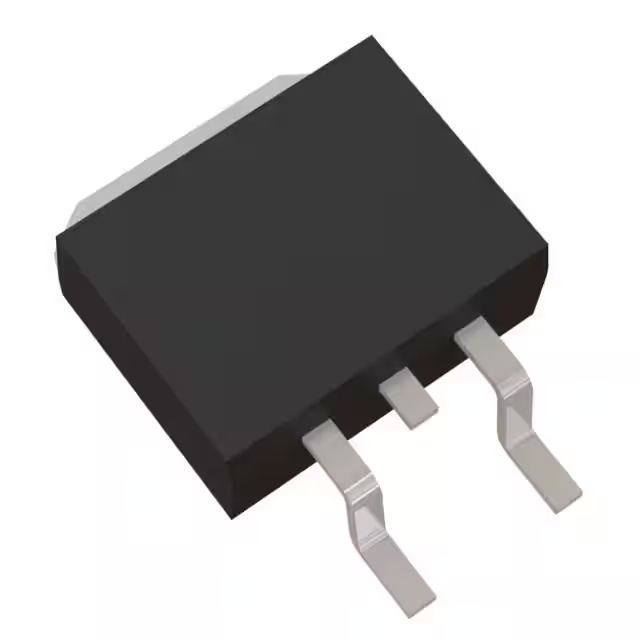
BLF188XR amplifier datasheet & price | schematic
- 品牌: 安普隆
- 下載: -
- 價格: 詢問
- 有存貨: 9766
- 技術: Si
- 獲得: -
- 運輸限制: -
- 包裹: -

訂單滿 HK$250.00 即可享有免運

快速回應,快速報價

閃電出貨,售後無憂

原廠通路,正品保證
Key Features of the BLF188XR
The BLF188XR is a high-performance LDMOS transistor designed for RF power applications. It’s commonly used in high-power amplifiers, offering excellent efficiency and linearity. This transistor supports a wide frequency range, making it ideal for applications like broadcast transmitters and radar systems. With a high power output and low distortion, the BLF188XR ensures reliable performance even in demanding environments. It also features a rugged construction, making it suitable for use in harsh conditions. Whether you’re working with telecommunications or broadcasting, the BLF188XR provides solid, efficient power amplification.
BLF188XR Pinout
| 密碼 | 引腳名稱 | 描述 |
|---|---|---|
| 1 | 流走 | The drain is the high-voltage terminal where the RF power is delivered to the load. |
| 2 | 門 | The gate controls the MOSFET’s switching, regulating the flow of current. Typically driven with a negative voltage. |
| 3 | 來源 | The source is the reference terminal, typically connected to ground or the negative side of the circuit. |
Pinout Usage and Notes
The BLF188XR is a high-power LDMOS transistor, and its pinout follows typical MOSFET configurations. For proper operation, ensure the gate is driven with the correct negative voltage to turn the transistor on, while the drain handles the RF output to the load. Proper heat management is critical as this device handles high power, and using adequate heatsinking is essential to prevent thermal failure. Be sure to connect the source to the negative side of your power supply for proper functionality.
BLF188XR Equivalent Models
| 模型 | Vds (Max) | Id (Max) | Pout (Max) | Gain | 封裝類型 |
|---|---|---|---|---|---|
| BLF188XR | 50伏 | 25A | 250W | 19分貝 | SOT-539 |
| MRF6VP5600H | 50伏 | 25A | 250W | 18.5dB | SOT-539 |
| MRF6VP5600N | 50伏 | 25A | 250W | 19分貝 | SOT-539 |
| NXP MRFE6VP61K | 50伏 | 25A | 250W | 18dB | SOT-539 |
Equivalent Models Usage and Notes
If you’re looking for alternatives to the BLF188XR, the MRF6VP5600H, MRF6VP5600N, and NXP MRFE6VP61K are all suitable replacements. These models offer similar power output and maximum drain-to-source voltage, making them interchangeable in most applications. Pay attention to the small differences in gain, as it might affect signal amplification in specific designs. All these models come in the same SOT-539 package, ensuring compatibility in terms of physical dimensions. Just be sure to check the application’s requirements for gain and thermal performance when choosing a replacement.
BLF188XR Amplifier Kit
The BLF188XR amplifier kit is designed to provide high-power amplification for RF applications. It features a robust design capable of delivering up to 250W output, making it ideal for broadcasting and communication systems. The kit comes with all the necessary components to build a high-performance amplifier, ensuring reliable performance in demanding environments. Whether you’re working on a new RF project or upgrading an existing system, this kit is a great choice for efficient, high-quality amplification.
BLF188XR Bias Current
The bias current for the BLF188XR is an essential parameter to ensure proper operation of the transistor. Correct biasing helps maintain optimal performance by preventing distortion and ensuring the device operates within its safe thermal limits. For the BLF188XR, the recommended bias current typically ranges from 200mA to 300mA, depending on the application and operating conditions. Proper adjustment of the bias current is critical for achieving maximum efficiency and reliability in high-power RF circuits.
BLF188XR Amplifier Circuit Analysis
The BLF188XR is a high-power LDMOS transistor commonly used in RF amplifier circuits. A typical application involves using the transistor in a push-pull configuration, often paired with another BLF188XR, to achieve higher output power and improved linearity. In such circuits, the input RF signal is fed through an input transformer, which provides impedance matching and ensures that the gate drive signals are properly balanced. The gates of the transistors are biased using a negative voltage, typically around -2V, to operate in Class AB mode, balancing efficiency and linearity.
The drain supply voltage is usually set at 50V, with the drain current adjusted to around 40mA per device. This setup allows for an output power of approximately 1400W at 108 MHz. Output matching is achieved using a broadband transformer, often with a 16:1 turns ratio, to match the low impedance of the transistor to the 50Ω load. Proper heat dissipation is critical, so a substantial heatsink is used to maintain safe operating temperatures.
When designing or building such an amplifier, it’s essential to ensure that all components are rated for the operating voltages and currents. Additionally, proper impedance matching throughout the circuit minimizes reflections and ensures efficient power transfer. Thermal management is crucial to prevent overheating and potential damage to the transistors. Lastly, always verify the biasing conditions and adjust them as needed to maintain optimal performance and prevent distortion or device failure.


