
CH341A Programmer Software & Driver
- 品牌: WCH(江蘇秦恆)
- 下載: -
- 價格: 詢問
- 有存貨: 9896
- 電壓 - 電源: 3.3伏
- Applications Function: -
- 協定: USB 2.0
- 包裹: SOP-28-300mil


訂單滿 HK$250.00 即可享有免運

快速回應,快速報價

閃電出貨,售後無憂

原廠通路,正品保證
Unboxing EEPROM BIOS USB Programmer CH341A
Ch341a
If you’re getting into programming or device development, the CH341A USB chip is something you’ll find super useful. It handles USB to serial, I²C, SPI, and even parallel communication, covering most scenarios you’ll run into. Since it meets USB 2.0 standards, it connects reliably with almost any device you have.
One great thing about the CH341A is its built-in SPI and I²C support. This makes it perfect if you’re flashing BIOS chips, EEPROMs, or working with microcontrollers. Plus, it’s extremely easy to set up—just a few external parts, and you’re good to go.
Another neat feature is its flexible voltage support. Whether your components run at 3.3V or 5V, this chip adjusts automatically. It’s widely used for things like BIOS updates, router firmware, or microcontroller projects, and there’s a huge community to help you along.
Drivers? No worries. It supports Windows, Linux, and macOS, making installation painless. Best of all, it’s super affordable, giving you great value without sacrificing performance.
Ch341a Pinout

| 密碼 | 引腳名稱 | 描述 |
|---|---|---|
| 1 | nACT | USB Transfer Active (Low-level active) |
| 2 | RSTI | Chip Reset Input (Low-level Reset) |
| 3 | IN7/nSIN/nAS | Parallel Input/Serial Input/Address Strobe |
| 4 | nROV/nAFD/nDS | Parallel Output/Strobe Output |
| 5 | TXD | UART Data Transmit (USB to Serial) |
| 6 | RXD | UART Data Receive (Serial to USB) |
| 7 | nINT/nACK | Parallel Port Interrupt Output |
| 8 | IN3/nSLCT | Parallel Port Input |
| 9 | V3 | Internal 3.3V Voltage Regulator Output |
| 10 | UD+ | USB Data Positive (D+) |
| 11 | UD- | USB Data Negative (D-) |
| 12 | 接地 | 地面 |
| 13 | XI | Crystal Input (12MHz) |
| 14 | XO | Crystal Output (12MHz) |
| 15 | nCTS/D0/CS0 | Parallel Input/Output D0, SPI Output Enable CS0 |
| 16 | nDSR/D1/CS1 | Parallel Input D1, SPI Chip Select CS1 |
| 17 | nRI/D2/CS2 | Parallel Input D2, SPI Chip Select CS2 |
| 18 | nDCD/D3/DCK | Parallel Input D3, SPI Clock |
| 19 | nOUT/D4/DOUT2 | Parallel Input D4, SPI Data Output (MOSI) |
| 20 | nDTR/D5/DOUT | Parallel Input D5, SPI Data Output (MOSI alternative) |
| 21 | nRST/D6/DIN2 | Parallel Input D6, SPI Data Input (MISO) |
| 22 | nSLP/D7/DIN | Parallel Input D7, SPI Data Input (MISO alternative) |
| 23 | SDA | I²C Data Line |
| 24 | SCL | I²C Clock Line |
| 25 | nRDY/nSTB/nWR | Parallel Port Status Output |
| 26 | TNOW/nINI/nRST | Status Transfer Output |
| 27 | nTEN/BUSY/nWAIT | Parallel Port Status/Busy Signal |
| 28 | 電壓控制電路 | Power Supply Input (Typically 5V) |
When you’re wiring up the CH341A chip, pay attention to a few things to keep your setup stable. First, pins 10 and 11 handle your USB data communication—try keeping your USB cables short and tidy, as long cables might cause data instability.
Next, pins 13 and 14 (XI, XO) connect to a 12MHz crystal along with two small capacitors (around 20pF each). Place these parts close to the chip for better reliability.
For the SPI interface (pins 15-22), double-check your connections carefully. Make sure MOSI (data out), MISO (data in), and CLK (clock signal) lines are clearly identified and correctly wired.
If you’re using the I²C interface (pins 23, 24), remember to include pull-up resistors—typically 4.7kΩ to 10kΩ—to ensure proper communication.
Regarding power, pin 28 takes in 5V and provides a regulated 3.3V output at pin 9. Be cautious about how much current you draw to avoid stressing the regulator.
Finally, always watch out for static electricity—it’s easy to damage the chip with static, so handle it carefully.
Ch341a Equivalent


| Parameter/Model | CH341A | FT232RL | PL2303HX | CP2102 |
|---|---|---|---|---|
| 製造商 | Nanjing Qinheng (CH) | FTDI | Prolific | Silicon Labs |
| Interface Type | USB to SPI/I2C/UART | USB to UART | USB to UART | USB to UART |
| USB標準 | USB 2.0 Full-Speed | USB 2.0 Full-Speed | USB 2.0 Full-Speed | USB 2.0 Full-Speed |
| SPI/I2C Support | 支援 | 不支援 | 不支援 | 不支援 |
| UART Support | 支援 | 支援 | 支援 | 支援 |
| Voltage Support | 3.3V/5V | 3.3V/5V | 3.3V/5V | 3.3伏 |
| 封裝類型 | SOP-28 | SSOP-28 | SSOP-28 | QFN-28, SSOP-28 |
| 常見應用 | USB to SPI Programmer, BIOS flashing, serial communication | USB to UART debugging, programming | USB to UART communication | USB to UART debugging |
| Driver Compatibility | Excellent | Excellent | Good | Excellent |
| Cost Advantage | Low cost | High cost | Medium cost | Moderate cost |
When you’re picking an alternative to the CH341A chip, always double-check that the replacement actually does what you need. For instance, the CH341A supports SPI and I²C interfaces, while chips like FT232RL, PL2303HX, or CP2102 usually handle only UART serial communication. So make sure your new chip meets your project’s requirements.
Also, pay attention to the packaging and pin layout. If the new chip doesn’t match your PCB’s layout, you might end up needing to redesign your board—something you’d definitely want to avoid.
Another critical point is voltage compatibility. Take the CP2102, for example; it’s mainly set up for 3.3V logic. Connecting it incorrectly could damage your equipment or cause unexpected behavior. Always verify the voltage levels match your application.
Finally, different chips might need different drivers. Before you switch, confirm the new chip’s drivers work well with your operating system to save yourself some headaches later on.
Ch341a Flash Programmer Circuit
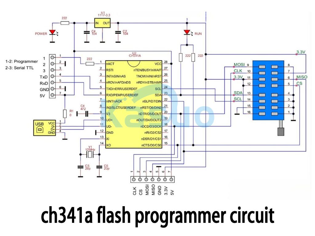
Here’s how your CH341A-based Flash programmer works: On the left, you’ve got your USB connector—it handles both power and data communication. The USB data lines (D+ and D-) link straight into the CH341A chip (UD+ and UD-).
Next, there’s a 12MHz crystal oscillator paired with two small capacitors (around 20pF each), making sure everything stays stable and your data transfers go smoothly.
At the top, you’ll notice a 1117-3.3 voltage regulator. It takes the USB’s 5V and drops it down neatly to a stable 3.3V to safely power your CH341A and the Flash chips you’re programming.
On the right side, there’s a handy ZIF socket—this is where you’ll insert your target chip. SPI pins (CLK, MOSI, MISO, CS) are clearly connected from this socket directly to the CH341A. There’s also an I²C interface (SDA, SCL) for programming EEPROM chips.
Overall, the setup is straightforward, giving you reliable USB-to-SPI/I²C communication, ideal for flashing BIOS, firmware, or EEPROMs easily.
Ch341a Bios Programmer Usage
When you’re ready to flash a BIOS using your CH341A programmer, make sure you insert the BIOS chip correctly into the programmer socket—line up the notch or dot with pin 1. If the chip is soldered onto your motherboard, no worries; you can use a clip adapter to program it directly, just double-check the orientation.
Next, plug the CH341A into your computer via USB, and it’ll usually auto-detect and install drivers. If not, you’ll need to install them manually.
Launch your CH341A software and click “Detect” to confirm it recognizes the BIOS chip. Then, click “Read” to save a backup of your original BIOS—trust me, you’ll thank yourself later if something goes wrong.
Now erase the old data by clicking “Erase,” open your new BIOS file, and hit “Program.” After flashing, use “Verify” to confirm everything matches up perfectly.
Always double-check the chip model and ensure you’re using the correct voltage (usually 3.3V). Also, don’t unplug anything during flashing—stay patient until it’s fully done!
更多類似商品

TPIC6C596PWG4
德州儀器
TPIC6C596PW
德州儀器

MC14557BDWR2G
安森美

74HCT595D,112
Nexperia美國公司

SN74AHC594D
德州儀器
CD4031BPWR
德州儀器
CD4035BPWR
德州儀器
CD74HCT166M
德州儀器
")
TC74HC165AP(F)
東芝半導體和存儲

SN74HC595ANSR
德州儀器

SN74LV166ADBR
德州儀器

BU4015BF-E2
羅姆半導體
也加入購物車

M4A3-192/96-10FAI
萊迪思半導體公司
CENGPXA270-312-10-550EC
Beacon EmbeddedWorks

AD6620ASZ-REEL
ADI公司

TLV9052IDDFR
德州儀器

PFS714EG
電力集成

MP174GJ-Z
單晶片電力系統公司

LTC2946CMS-1#TRPBF
ADI公司

TLV2462QDRQ1
德州儀器
DS90UH949TRGCTQ1
德州儀器

CYUSB3328-88LTXIT
賽普拉斯半導體公司

GT4123-CKA
根努姆

89HP0604SZBABG
瑞薩電子美國公司
相關產品
TPIC6C596PWG4
德州儀器
TPIC6C596PW
德州儀器
MC14557BDWR2G
安森美
74HCT595D,112
Nexperia美國公司
SN74AHC594D
德州儀器
CD4031BPWR
德州儀器
CD4035BPWR
德州儀器
CD74HCT166M
德州儀器
TC74HC165AP(F)
東芝半導體和存儲
SN74HC595ANSR
德州儀器
SN74LV166ADBR
德州儀器
BU4015BF-E2
羅姆半導體
CD4094BPW
德州儀器
SN74LV595AQPWRQ1
德州儀器

SN74LV166ADGVR
德州儀器

CD74HC595NSR
德州儀器
SN74LV595ANSR
德州儀器
SN74LV594ADBR
德州儀器

SN74F299DWR
德州儀器
BU4021BF-E2
羅姆半導體

74AHCT164BQ-Q100X
Nexperia美國公司
74HCT597D-Q100J
Nexperia美國公司
SN74LV165APWT
德州儀器
SN74AHCT594DBR
德州儀器
74HC594D-Q100,118
Nexperia美國公司

CD74HC195NSR
德州儀器

74LVC594ABQ-Q100X
Nexperia美國公司

74AHCT164D-Q100J
Nexperia美國公司

74AHCT164PW-Q100J
Nexperia美國公司
NPIC6C596BQ-Q100,1
Nexperia美國公司
請發送 RFQ,我們將立即回覆。
