
HMC6343 datasheet, price & Arduino | breakout & compass
- 軸: X、Y、Z
- Measuring Range: ±2高斯
- 用於測量: 航向、俯仰與橫滾
- 包裹: 管子


訂單滿 HK$250.00 即可享有免運

快速回應,快速報價

閃電出貨,售後無憂

原廠通路,正品保證
Trying to use an HMC6343 compass as an IMU
HMC6343
The HMC6343 is a compact, high-performance module that combines a 3-axis magnetometer and accelerometer. This makes it perfect for applications that need precise orientation and navigation, like robotics, drones, and wearables. It’s designed for accuracy, especially in magnetic field measurements, so it’s great when heading data is crucial. Plus, it uses low power, making it ideal for battery-powered devices.
It communicates via I2C or SPI, so it’s easy to connect to microcontrollers or other systems for real-time control. The HMC6343 also works as a digital compass, giving you heading info based on the Earth’s magnetic field, which is key for navigation. And it’s built with calibration and sensor fusion algorithms to ensure accurate readings with minimal manual setup.
HMC6343 Pinout and Connections

| 密碼 | 引腳名稱 | 描述 |
|---|---|---|
| 1 | 電源電壓 | Power Supply (3.3V to 5V) |
| 2 | 接地 | 地面 |
| 3 | SDA | Serial Data (I2C or SPI) |
| 4 | SCL | Serial Clock (I2C or SPI) |
| 5 | CS | Chip Select (SPI) |
| 6 | INT | Interrupt Output (Active Low) |
| 7 | DRDY | Data Ready Output (Active Low) |
| 8 | NC | No Connection (Reserved) |
| 9 | NC | No Connection (Reserved) |
| 10 | NC | No Connection (Reserved) |
The VDD pin (Pin 1) powers the HMC6343, so make sure to provide a stable voltage between 3.3V and 5V for it to run smoothly. GND (Pin 2) is where you’ll connect the ground, ensuring everything has a solid reference.
For I2C communication, connect the SDA (Pin 3) and SCL (Pin 4) pins to the I2C lines on your microcontroller. If you’re using SPI, the CS pin (Pin 5) needs to be pulled low to start communication with the HMC6343.
The DRDY pin (Pin 7) will go low when new data is ready to be read. This is handy for real-time data retrieval, helping you sync data reading with your system’s timing.
HMC6343 Equivalent Compass Sensor

| Feature / Model | HMC6343 | HMC5883L | LSM303D | QMC5883L |
|---|---|---|---|---|
| Sensor Type | 3-Axis Magnetometer + Accelerometer | 3-Axis Magnetometer | 3-Axis Magnetometer + Accelerometer | 3-Axis Magnetometer |
| Output Interface | I2C / SPI | I2C | I2C | I2C |
| 電源 | 3.3V to 5V | 2.16V to 3.6V | 2.16V to 3.6V | 1.8V to 3.6V |
| 工作溫度 | -40°C 至 +85°C | -40°C 至 +85°C | -40°C 至 +85°C | -40°C 至 +85°C |
| 準確性 | ±1.5° (magnetometer) | ±1° (magnetometer) | ±2° (magnetometer) | ±1° (magnetometer) |
| 封裝類型 | 10-pin package (LGA) | 10-pin package (LGA) | 10x10mm, 6-pin package | 3x3mm, 6-pin package |
| Sensitivity | 0.5 µT / LSB | 0.6 µT / LSB | 0.6 µT / LSB | 0.6 µT / LSB |
| Magnetic Range | ±8 Gauss | ±8 Gauss | ±16 Gauss | ±8 Gauss |
| Accel Range | ±2g, ±4g, ±8g, ±16g | Not available | ±2g, ±4g, ±8g, ±16g | Not available |
| Built-in Calibration | 是的 | 是的 | 是的 | 是的 |
When looking for a replacement for the HMC6343, think about what features you need. If you only need a magnetometer, the HMC5883L or QMC5883L are good options. They’re small, accurate, and have low power consumption, which makes them perfect for compact, battery-powered devices. The downside is that they don’t have an accelerometer, so if you need tilt measurement too, you’ll want to consider the LSM303D. It has both a magnetometer and an accelerometer, making it a better fit for more complex projects, though it comes in a larger package.
Also, be sure to check that the voltage and communication interface (I2C/SPI) match your system’s needs.
HMC6343 Compass Sensor Circuit Example
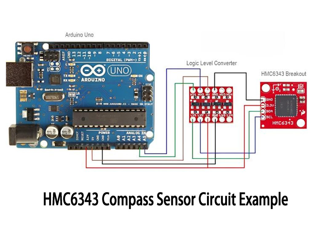
The HMC6343 sensor combines a 3-axis magnetometer and accelerometer, giving you both direction and acceleration data. It’s great for applications like navigation, robotics, and drones.
In this circuit, the HMC6343 communicates with an Arduino through the I2C interface using the SDA (data) and SCL (clock) pins. The magnetometer measures the magnetic field to determine direction, while the accelerometer measures motion and tilt.
Since Arduino uses 5V for I2C and the HMC6343 needs 3.3V, a logic level converter is used to safely match the voltage levels. This ensures smooth communication between the sensor and Arduino.
This setup is perfect for tracking direction and motion in robots, drones, or even wearable devices, offering accurate positioning and orientation data.
HMC6343 I2C Communication Setup
To get the HMC6343 working with an Arduino, you’ll need a few key components. First, connect the HMC6343’s SDA and SCL pins to the Arduino’s corresponding pins (A4 and A5 on Arduino Uno) using a logic level converter to match the 3.3V logic of the sensor with the 5V of Arduino. After wiring everything up, you can use the I2C protocol to communicate between the two.
Next, in the Arduino IDE, make sure you have the Wire library installed for I2C communication. Then, upload a simple sketch to start reading sensor data. Once everything’s set up, you’ll see data coming from the sensor in the Serial Monitor, which you can then use to track direction or measure tilt.
更多類似商品

ER-QA-01C
Ericco Inertial System

ER-QA-01A
Ericco Inertial System

ER-QA-01B
Ericco Inertial System
ER-QA-03A
Ericco Inertial System
PXLS90733AESR2
恩智浦美國公司

IAC-HIRES-I-Y-01-22-0100-1-XX.X
RECOVIB
IAC-HIRES-I-Y-01-22-1000-1-XX.X
RECOVIB
IAC-HIRES-I-Z-01-22-0250-1-XX.X
RECOVIB
IAC-HIRES-I-Y-01-22-0250-1-XX.X
RECOVIB
IAC-HIRES-I-X-01-22-0500-1-XX.X
RECOVIB
IAC-HIRES-I-X-01-22-0100-1-XX.X
RECOVIB
IAC-HIRES-I-Z-01-22-0100-1-XX.X
RECOVIB
也加入購物車

SCM7B47K-04A
DATAFORTH

TSMP6000TT
Vishay 半導體光電部門
E52-CA22A D=1 NETU 1M
歐姆龍自動化與安全

MAX1617AMEE+T
ADI公司/Maxim Integrated

T0218
Comet America, LP

PDV-P7003
先進的光子學

503011
Elesa 美國公司

EKMC1610111
松下電工
POS287312
霍尼韋爾感測與生產力解決方案

M52173/12VDC
Eclipse Magnetics Ltd

SCA3000-E05
村田電子
D6F 0026D
歐姆龍電子公司-EMC事業部
相關產品
ER-QA-01C
Ericco Inertial System
ER-QA-01A
Ericco Inertial System
ER-QA-01B
Ericco Inertial System
ER-QA-03A
Ericco Inertial System
PXLS90733AESR2
恩智浦美國公司
IAC-HIRES-I-Y-01-22-0100-1-XX.X
RECOVIB
IAC-HIRES-I-Y-01-22-1000-1-XX.X
RECOVIB
IAC-HIRES-I-Z-01-22-0250-1-XX.X
RECOVIB
IAC-HIRES-I-Y-01-22-0250-1-XX.X
RECOVIB
IAC-HIRES-I-X-01-22-0500-1-XX.X
RECOVIB
IAC-HIRES-I-X-01-22-0100-1-XX.X
RECOVIB
IAC-HIRES-I-Z-01-22-0100-1-XX.X
RECOVIB
IAC-HIRES-I-X-01-22-0250-1-XX.X
RECOVIB
IAC-HIRES-I-X-01-22-1000-1-XX.X
RECOVIB
PMMA8205KEG
恩智浦美國公司
PMMA3221KEG
恩智浦美國公司
PMMA3204KEG
恩智浦美國公司
PMMA3202KEG
恩智浦美國公司
PMMA3201KEG
恩智浦美國公司
PMMA2301KEG
恩智浦美國公司
PMMA2300KEG
恩智浦美國公司
PMMA2244KEG
恩智浦美國公司
PMMA2241KEG
恩智浦美國公司
PMMA2240KEG
恩智浦美國公司
PMMA2206KEG
恩智浦美國公司
PMMA2204KEG
恩智浦美國公司
PMMA2202KEG
恩智浦美國公司
PMMA2201KEG
恩智浦美國公司
PMMA1270KEG
恩智浦美國公司
PMMA1260KEG
恩智浦美國公司
請發送 RFQ,我們將立即回覆。
