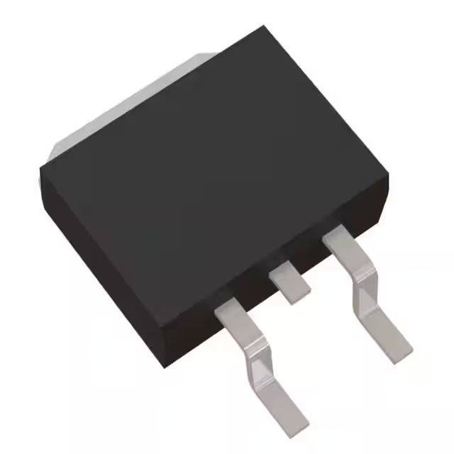
IRF4905LPBF 資料表、價格、pdf
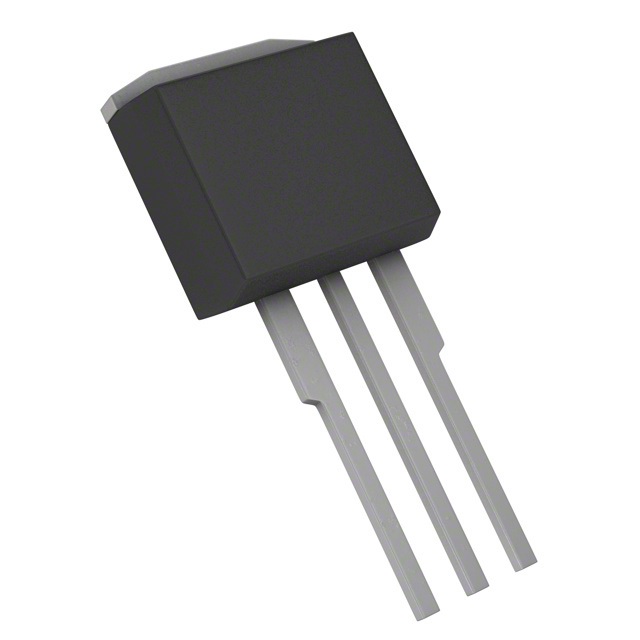
- 供應商元件封裝: TO-262
- 場效電晶體類型: P溝道
- 漏源電壓 (Vdss): 55 V
- 包裹: TO-262-3 Long Leads, I2PAK, TO-262AA

訂單滿 HK$250.00 即可享有免運

快速回應,快速報價

閃電出貨,售後無憂

原廠通路,正品保證
Key Features of the IRF4905 MOSFET
這 IRF4905 is a high-performance N-channel MOSFET designed for low-voltage, high-current applications. It offers a low RDS(on) (drain-source resistance), which means it can handle higher currents with less power loss. This makes it ideal for power supply systems, motor drivers, and battery-powered devices. With a maximum VDS (drain-source voltage) of 55V and a current rating of 74A, the IRF4905 can drive significant loads efficiently. Its fast switching speed and robust protection features, including thermal and overcurrent protection, ensure reliable performance even in demanding environments. Whether you’re building power converters or high-power switches, the IRF4905 is a solid choice for your design.
IRF4905 Pinout
| 別針 | Label | 描述 |
|---|---|---|
| 1 | Gate (G) | The gate terminal, used to control the MOSFET’s switching. Apply voltage here to turn the MOSFET on or off. |
| 2 | Drain (D) | The drain terminal, where the load is connected. This is the output terminal of the MOSFET. |
| 3 | Source (S) | The source terminal, connected to the negative side of the load or ground in a typical low-side switching configuration. |
Using the IRF4905 Pinout
To use the IRF4905, apply the control voltage to the 門 (Pin 1) to turn the MOSFET on or off. The 流走 (Pin 2) connects to the load, while the 來源 (Pin 3) is typically connected to the ground or the negative side of the circuit. When a voltage is applied to the gate that is higher than the source by a certain threshold (typically 4-10V), the MOSFET turns on, allowing current to flow from the drain to the source. Be sure not to exceed the maximum gate-source voltage (Vgs) to avoid damaging the MOSFET.
IRF4905 Equivalent Models
Here’s a comparison of equivalent MOSFETs with similar packaging and performance:
| 模型 | Voltage Rating | Current Rating | RDS(on) | 封裝類型 | Gate Threshold Voltage |
|---|---|---|---|---|---|
| IRF4905 | 55伏 | 74A | 0.02Ω | TO-220 | 4V-6V |
| IRLZ44N | 55伏 | 47A | 0.022Ω | TO-220 | 1V-2V |
| IRFZ44N | 55伏 | 49A | 0.022Ω | TO-220 | 2V-4V |
| STP55NF06L | 60伏 | 55A | 0.014Ω | TO-220 | 1V-2V |
Substitution Tips
When replacing the IRF4905, make sure the voltage rating, current rating, 和 RDS(on) (resistance) are similar to ensure reliable operation. For example, the IRLZ44N 和 IRFZ44N are good alternatives, with slightly lower current ratings and gate threshold voltages, making them suitable for lower-voltage applications. The STP55NF06L has a higher voltage rating of 60V, but its RDS(on) is slightly lower, making it a good option if you need better efficiency at higher voltages. Always ensure the gate threshold voltage and package type match your design for proper function.
IRF4905 H-Bridge with Arduino for Parallax
這 IRF4905 MOSFET is a great choice for building an H-Bridge motor driver circuit with an Arduino, perfect for controlling DC motors in projects like robotics or automation. In a typical setup, you can use four IRF4905 MOSFETs to form the H-Bridge, allowing you to control the direction and speed of the motor by applying PWM signals from the Arduino. For Parallax-based projects, this setup enables precise motor control with smooth operation. By using the H-Bridge, you can easily switch the polarity of the motor’s power, controlling both forward and reverse motion. Just make sure to use the right gate drive voltage to fully switch the MOSFETs, and protect the circuit with proper flyback diodes for safe operation.
IRF4905 Circuit Diagram and Analysis
這 IRF4905 is a P-channel MOSFET commonly used in power switching applications. A typical circuit utilizing the IRF4905 is an H-Bridge configuration, which allows for bidirectional control of DC motors.
H-Bridge Circuit Using IRF4905
In this configuration, four MOSFETs are arranged to control the direction of current through a motor, enabling forward and reverse operation. The IRF4905 is often used as the high-side switch in this arrangement due to its P-channel characteristics.
Key Components:
-
IRF4905 (P-channel MOSFET): Used for high-side switching.
-
IRFZ44N (N-channel MOSFET): Used for low-side switching.
-
Gate Drivers: To properly switch the MOSFETs, especially the high-side IRF4905.
-
Flyback Diodes: To protect against voltage spikes caused by the inductive load (motor).
Operation:
-
When the high-side MOSFET (IRF4905) is turned on and the low-side MOSFET is turned off, current flows through the motor in one direction.
-
Reversing the states of the MOSFETs allows current to flow in the opposite direction, reversing the motor’s rotation.
Considerations:
-
Ensure that the gate drive voltage is sufficient to fully turn on the IRF4905.
-
Use appropriate flyback diodes to protect the MOSFETs from voltage spikes.
-
Proper heat sinking is necessary to dissipate the power loss in the MOSFETs.
For a detailed schematic and further information, you can refer to resources like BristolWatch 或者 Electronics Stack Exchange.
