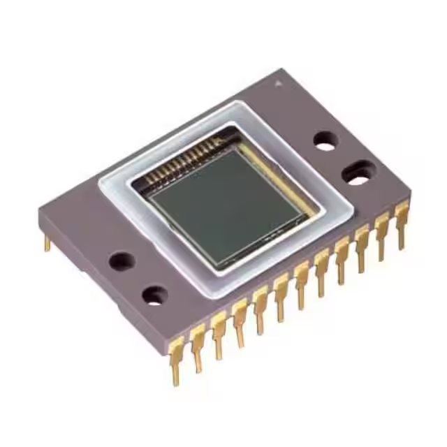
MMC5983MA datasheet & Arduino | price
- 技術: 磁阻
- 軸: X、Y、Z
- 輸出類型: I²C、SPI
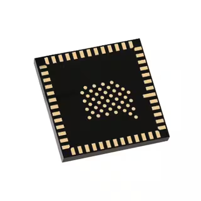
- 包裹: 16-LGA (3x3)

訂單滿 HK$250.00 即可享有免運

快速回應,快速報價

閃電出貨,售後無憂

原廠通路,正品保證
Key Features of the MMC5983MA
The MMC5983MA is a high-precision 3-axis magnetometer designed for accurate magnetic field measurement. With its small footprint and low power consumption, it’s perfect for portable and wearable applications, such as compasses and navigation systems. This sensor provides high resolution, offering precise magnetic data with minimal noise, even in challenging environments. The MMC5983MA is easy to integrate with microcontrollers via I2C or SPI, making it ideal for various embedded system projects. Whether you’re building a GPS module, motion tracking system, or other positioning-based devices, this sensor delivers reliable performance in compact form.
MMC5983MA Pinout
| 密碼 | 引腳名稱 | 描述 |
|---|---|---|
| 1 | 電源電壓 | Power supply pin. Connect to a 1.8V to 3.6V supply for proper operation. |
| 2 | 接地 | Ground pin. Connect to the system ground. |
| 3 | SCL | Serial Clock for I2C communication. Connect to the clock pin of the microcontroller. |
| 4 | SDA | Serial Data for I2C communication. Connect to the data pin of the microcontroller. |
| 5 | DRDY | Data Ready. Output signal that indicates when new data is available for reading. |
| 6 | CS | Chip Select for SPI communication. This pin is used to activate the device for SPI communication. |
| 7 | SDI | Serial Data Input for SPI communication. Connect to the microcontroller’s MOSI pin. |
| 8 | SDO | Serial Data Output for SPI communication. Connect to the microcontroller’s MISO pin. |
| 9 | VDDIO | I/O supply pin. Typically connected to 1.8V to 3.6V, depending on logic level. |
Pinout Usage and Notes
The MMC5983MA uses both I2C and SPI interfaces for communication, so you’ll select the appropriate pins based on your chosen interface. For I2C, you’ll use the SDA and SCL pins, while for SPI, you’ll use CS, SDI, and SDO pins. The DRDY pin is useful for indicating when the sensor has new data ready to be read, ensuring you’re always working with the most up-to-date measurements. Make sure to connect VDD to a suitable power supply and ground the GND pin properly to avoid errors in sensor readings.
MMC5983MA Equivalent Models
| 模型 | 介面 | 電源電壓 | Output Data Rate | 準確性 | 封裝類型 |
|---|---|---|---|---|---|
| MMC5983MA | I2C/SPI | 1.8V to 3.6V | 10Hz to 800Hz | ±0.1µT | LGA-12 |
| HMC5883L | I2C | 2.16V to 3.6V | 0.75Hz to 8Hz | ±1.0µT | LGA-16 |
| LIS3MDL | I2C | 2.16V to 3.6V | 10Hz to 80Hz | ±0.1µT | LGA-16 |
| AK8963 | I2C | 2.5V to 3.6V | 8Hz to 100Hz | ±0.15µT | QFN-16 |
Equivalent Models Usage and Notes
If you’re looking for alternatives to the MMC5983MA, models like the HMC5883L, LIS3MDL, and AK8963 can serve similar purposes in magnetic field sensing applications. These sensors also support I2C communication and offer varying degrees of accuracy and output data rates. The HMC5883L has a slightly lower accuracy compared to the MMC5983MA, but it still performs well for most navigation applications. The LIS3MDL is a good option if you need a similar accuracy with a slightly broader output data rate range. The AK8963 is another viable alternative with a different package type but comparable performance. When choosing a replacement, ensure that the data rate, accuracy, and interface type match your specific needs for seamless integration.
Using the MMC5983MA with Arduino
Integrating the MMC5983MA with an Arduino is simple and efficient for adding magnetic sensing capabilities to your projects. By connecting the sensor to the Arduino using either I2C or SPI communication, you can easily retrieve magnetic field data. With its high precision and low power consumption, the MMC5983MA is perfect for applications like compasses or navigation systems. Simply install the necessary library, connect the sensor to your Arduino board, and start reading data with minimal setup. Whether you’re building a robot or working on a positioning system, this sensor provides reliable performance.
MMC5983MA Circuit Diagram and Analysis
The MMC5983MA is a high-precision 3-axis magnetometer designed for accurate magnetic field measurement. Its application circuit typically involves connecting the sensor to a microcontroller via the I2C or SPI interface for data communication. Additionally, a 3.0V power supply is required to operate the module, as it is not 5V-tolerant. A logic level converter is often used to interface the 3.3V logic of the MMC5983MA with the 5V logic of common microcontrollers like the Arduino.
Key Components in the Circuit
-
Microcontroller (e.g., Arduino): Acts as the host processor, managing communication with the MMC5983MA module.
-
MMC5983MA Module: The UWB transceiver responsible for sending and receiving data.
-
Logic Level Converter: Ensures safe communication between the 3.3V MMC5983MA and 5V microcontroller.
-
3.3V Power Supply: Provides the necessary voltage for the MMC5983MA module.
-
Antenna: Facilitates UWB signal transmission and reception.
Circuit Diagram
Analysis
In this configuration, the microcontroller communicates with the MMC5983MA module via I2C or SPI, utilizing pins for clock (SCK), master-out-slave-in (MOSI), master-in-slave-out (MISO), and chip select (CS) for SPI communication, or data (SDA) and clock (SCL) for I2C communication. The logic level converter ensures that the voltage levels between the microcontroller and the MMC5983MA are compatible, preventing potential damage to the module. The 3.3V power supply is crucial, as applying 5V directly to the MMC5983MA can permanently damage it. The antenna is essential for UWB communication, enabling accurate distance measurements and positioning.
Usage Notes
-
電源: Always use a 3.3V supply for the MMC5983MA module.
-
Logic Level Conversion: Employ a logic level converter when interfacing with 5V logic systems.
-
Antenna Placement: Position the antenna away from metal objects to minimize signal interference.
-
通訊介面: Choose between I2C and SPI based on your system requirements and available microcontroller pins.
-
PCB Design: For custom PCBs, refer to the MMC5983MA module’s land pattern and layout guidelines to ensure proper signal integrity and power distribution.


