
RP2040 LEDs Not Working, Zero SPI Pinout
- 品牌: 樹莓派
- 下載: -
- 價格: 詢問
- 有存貨: 6736
- 輸入/輸出數量: 30
- CPU 最大速度: 133MHz
- DAC(位元): -
- 包裹: LQFN-56(7x7)


訂單滿 HK$250.00 即可享有免運

快速回應,快速報價

閃電出貨,售後無憂

原廠通路,正品保證
RP2040
If you’re looking for a cheap and powerful microcontroller to play with, check out the Raspberry Pi RP2040. It’s the first MCU made by Raspberry Pi, with two Cortex-M0+ cores running at 133MHz—great for multitasking. It doesn’t have internal flash memory, but you can easily add external QSPI Flash, and most development boards have this already sorted.
The coolest part? Its programmable I/O (PIO) lets you simulate protocols like VGA, DVI, I²S, or even drive WS2812 LED strips—all just through code. It also has flexible USB support, so making keyboards, USB storage devices, or MIDI controllers is straightforward. Plus, it’s low-power, perfect for portable projects.
Overall, whether you’re an Arduino fan, into MicroPython, or just want something versatile and fun, the RP2040 is perfect for your next creative project.
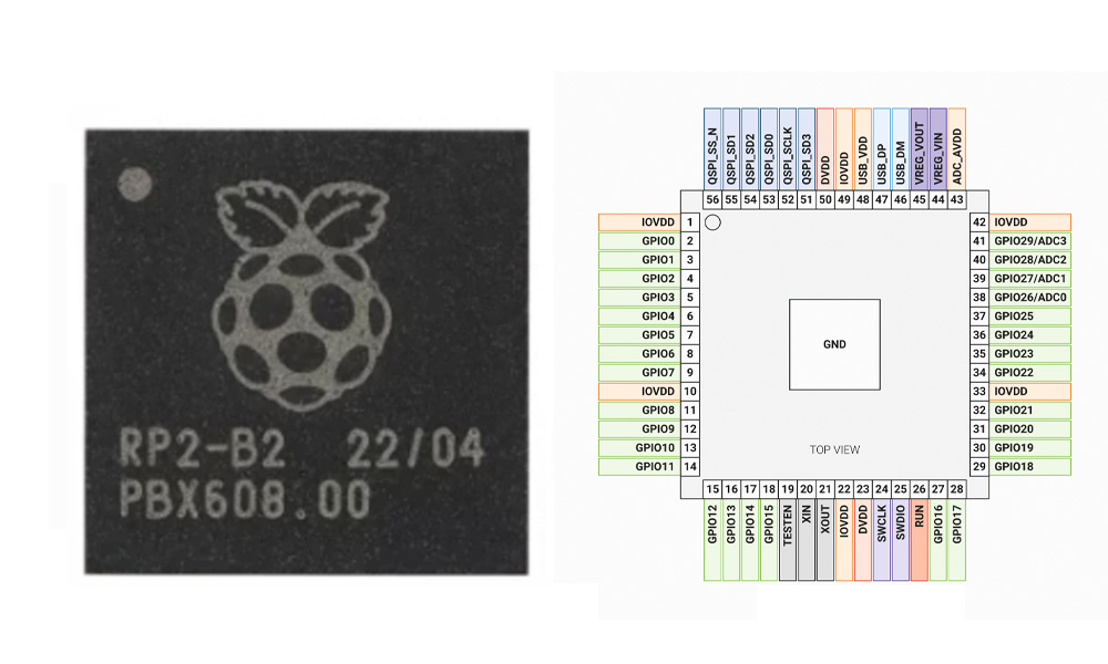
RP2040 Pinout
| 密碼 | 引腳名稱 | 功能描述 |
|---|---|---|
| 1 | 接地 | Ground (power negative) |
| 2 | GPIO0 | GPIO / ADC0 / SPI0 RX |
| 3 | GPIO1 | GPIO / ADC1 / SPI0 CSn |
| 4 | GPIO2 | GPIO / ADC2 / SPI0 SCK |
| 5 | GPIO3 | GPIO / ADC3 / SPI0 TX |
| 6 | GPIO4 | GPIO / UART1 TX / I2C0 SDA |
| 7 | GPIO5 | GPIO / UART1 RX / I2C0 SCL |
| 8 | GPIO6 | GPIO / SPI0 RX / SPI1 RX |
| 9 | GPIO7 | GPIO / SPI0 CSn / SPI1 CSn |
| 10 | GPIO8 | GPIO / SPI0 SCK / SPI1 SCK |
| 11 | GPIO9 | GPIO / SPI0 TX / SPI1 TX |
| 12 | GPIO10 | GPIO / UART1 TX / I2C1 SDA |
| 13 | GPIO11 | GPIO / UART1 RX / I2C1 SCL |
| 14 | GPIO12 | GPIO / SPI1 RX |
| 15 | GPIO13 | GPIO / SPI1 CSn |
| 16 | GPIO14 | GPIO / SPI1 SCK |
| 17 | GPIO15 | GPIO / SPI1 TX |
| 18 | GPIO16 | GPIO / UART0 TX / I2C0 SDA |
| 19 | GPIO17 | GPIO / UART0 RX / I2C0 SCL |
| 20 | GPIO18 | GPIO / SPI0 RX / SPI1 RX |
| 21 | GPIO19 | GPIO / SPI0 CSn / SPI1 CSn |
| 22 | GPIO20 | GPIO / SPI0 SCK / SPI1 SCK |
| 23 | GPIO21 | GPIO / SPI0 TX / SPI1 TX |
| 24 | GPIO22 | GPIO / UART0 TX / I2C1 SDA |
| 25 | GPIO23 | GPIO / UART0 RX / I2C1 SCL |
| 26 | GPIO24 | 通用輸入輸出 |
| 27 | GPIO25 | GPIO / onboard LED (some boards) |
| 28 | GPIO26/ADC0 | GPIO / ADC0 |
| 29 | GPIO27/ADC1 | GPIO / ADC1 |
| 30 | GPIO28/ADC2 | GPIO / ADC2 |
| 31 | ADC_AVREF | ADC reference voltage input |
| 32 | 3V3 | 3.3V power input/output |
| 33 | RUN | Run / Reset / Enable input (high active) |
| 34 | USB_DM | USB differential signal D- |
| 35 | USB_DP | USB differential signal D+ |
| 36 | 接地 | 地面 |
| 37 | SWCLK | SWD clock debug interface |
| 38 | SWDIO | SWD data debug interface |
| 39 | QSPI_SD1 | QSPI Flash Data 1 (for external Flash) |
| 40 | QSPI_SD2 | QSPI Flash Data 2 |
| 41 | QSPI_SD0 | QSPI Flash Data 0 |
| 42 | QSPI_SS | QSPI Flash Chip Select |
| 43 | QSPI_SCLK | QSPI Flash Clock |
| 44 | QSPI_SD3 | QSPI Flash Data 3 |
| 45 | 接地 | 地面 |
| 46 | VREG_IN | LDO Regulator Input |
| 47 | VREG_VOUT | LDO Regulator Output |
| 48 | USB_VDD | USB 1.1 PHY Power Input |
| 49 | 接地 | 地面 |
| 50 | USB_DM | USB differential signal D- (same as pin 34) |
| 51 | USB_DP | USB differential signal D+ (same as pin 35) |
| 52 | VBUS | USB 5V power input (detection / power management) |
| 53 | XIN | Crystal input (external clock) |
| 54 | XOUT | Crystal output (external clock) |
| 55 | 接地 | 地面 |
| 56 | TEST/NC | Factory test / Not connected |
When you’re working with the RP2040, its GPIO pins are extremely flexible. Almost any GPIO pin can handle functions like SPI, I2C, UART, PWM—just configure them in software. But keep in mind, ADC functions are only on GPIO26, 27, and 28, don’t mix those up if you’re measuring analog voltages.
Also, the USB interface uses pins 34 (USB_DM) and 35 (USB_DP), and you’ll need proper matching resistors. If you’re connecting external Flash memory, pins 39 to 44 are essential. The RUN pin resets or puts the chip into sleep mode when pulled low; adding a button here makes debugging easier.
The RP2040 comes in a small QFN-56 package, so be careful soldering to avoid shorts. Stick to 3.3V max for all IO pins, and don’t leave unused pins floating. Keep your power supply stable, and you’ll avoid many headaches.
Overall, the RP2040 is super user-friendly for creative projects—just pay attention to ADC, USB, and Flash connections, and you’ll have smooth sailing.
RP2040 Equivalent
| 範圍 | RP2040 | ESP32-S3-PICO-1 |
|---|---|---|
| 核心架構 | Dual-core ARM Cortex-M0+ | Dual-core Tensilica LX7 + FPU |
| Main Frequency | 133 MHz | 240 MHz |
| 靜態記憶體 | 264 KB | 512 KB |
| Flash (Internal/External) | External QSPI Flash | Embedded 8MB Flash + 2MB PSRAM |
| GPIO Count | 30 | 45 |
| ADC通道 | 3 channels (12-bit) | None (external ADC required) |
| USB OTG | 支援 | 支援 |
| Wireless Connectivity | Not supported | Supports Wi-Fi + Bluetooth LE |
| 工作電壓 | 1.8–3.3 V | 3.0–3.6 V |
If you’re looking to replace your RP2040 without redesigning your PCB, the ESP32-S3-PICO-1 is an excellent upgrade. It offers significantly better performance, built-in 8MB Flash, Wi-Fi, and Bluetooth. However, you should keep a few things in mind: it doesn’t have built-in ADC channels, so you’ll need an external ADC chip if required. Also, it doesn’t support RP2040’s unique PIO features like emulating VGA or controlling WS2812 LEDs directly.
Another thing to consider is power supply—RP2040 accepts voltages from 1.8 to 3.3V, but the ESP32-S3 needs a stable 3.0 to 3.6V supply. If your project doesn’t require wireless features, you can disable Wi-Fi and Bluetooth in software to reduce power usage.
Overall, if these points aren’t deal-breakers, ESP32-S3-PICO-1 is a powerful and convenient upgrade from the RP2040.
RP2040 Development Board Circuit
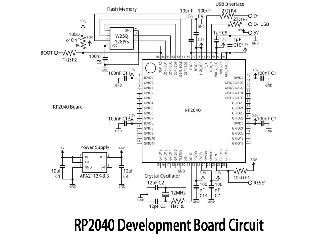
When building your RP2040 board, focus on these points: use APA2112K-3.3 to convert 5V to stable 3.3V with capacitors; 12MHz crystal provides stable clock; W25Q128JV Flash connects via QSPI; USB with 27Ω resistors enables easy programming; RESET and BOOT pins use pull-up resistors and buttons for easy operation mode changes; add 100nF decoupling capacitors near power pins. All IO pins are exposed for convenient expansion.
RP2040 USB Programming Example
Using RP2040 as a USB CDC virtual serial device is easy. Just connect your RP2040 board directly via USB—no extra wiring required. In Arduino IDE, select “Raspberry Pi Pico,” and the serial port will be auto-detected.
Your Arduino code just initializes serial communication, and once plugged in, your RP2040 appears as a virtual COM port. You can communicate with it directly using Arduino’s Serial Monitor or tools like Putty. Anything you send gets echoed back immediately.
Quick tip: The baud rate setting doesn’t actually matter for USB CDC—any number works fine. If your computer doesn’t detect the device, try using a better-quality USB cable.
RP2040 Raspberry Pi Pico Project
If you’re looking for a simple but useful RP2040 project, try building a temperature and humidity monitor with a Raspberry Pi Pico and a DHT22 sensor. Wiring is straightforward: VCC, GND, and DATA pins connect to the Pico’s 3.3V, GND, and GP15 respectively, with a 4.7kΩ resistor between DATA and VCC.
Using Arduino IDE, a few lines of code will have your sensor running. Connect it to your computer via USB to view real-time data. For upgrades, consider adding an OLED screen or an ESP8266 Wi-Fi module to enable remote monitoring and data logging.
更多類似商品

TPIC6C596PWG4
德州儀器
TPIC6C596PW
德州儀器

MC14557BDWR2G
安森美

74HCT595D,112
Nexperia美國公司

SN74AHC594D
德州儀器
CD4031BPWR
德州儀器
CD4035BPWR
德州儀器
CD74HCT166M
德州儀器
")
TC74HC165AP(F)
東芝半導體和存儲

SN74HC595ANSR
德州儀器

SN74LV166ADBR
德州儀器

BU4015BF-E2
羅姆半導體
也加入購物車

CY7C419-10JC
賽普拉斯半導體公司
Exposed-Pad.jpg "TPS54120RGYR")
TPS54120RGYR
德州儀器
ZSSC4165DE1B
IDT,整合設備技術公司

CS5366-DQZ
Cirrus Logic公司
37C654BQFP
簡訊中心

STM8S903K3T6CTR
意法半導體

MCP609T-I/SL
微晶片技術

CMX865AE4-TR1K
CML微電路
MIC5305-3.0TD5
麥克雷爾公司

FDC37C669QFP
簡訊中心

CD74HCT164ER2489
哈里斯公司

DS1013-25+
ADI公司/Maxim Integrated
相關產品
TPIC6C596PWG4
德州儀器
TPIC6C596PW
德州儀器
MC14557BDWR2G
安森美
74HCT595D,112
Nexperia美國公司
SN74AHC594D
德州儀器
CD4031BPWR
德州儀器
CD4035BPWR
德州儀器
CD74HCT166M
德州儀器
TC74HC165AP(F)
東芝半導體和存儲
SN74HC595ANSR
德州儀器
SN74LV166ADBR
德州儀器
BU4015BF-E2
羅姆半導體
CD4094BPW
德州儀器
SN74LV595AQPWRQ1
德州儀器

SN74LV166ADGVR
德州儀器

CD74HC595NSR
德州儀器
SN74LV595ANSR
德州儀器
SN74LV594ADBR
德州儀器

SN74F299DWR
德州儀器
BU4021BF-E2
羅姆半導體

74AHCT164BQ-Q100X
Nexperia美國公司
74HCT597D-Q100J
Nexperia美國公司
SN74LV165APWT
德州儀器
SN74AHCT594DBR
德州儀器
74HC594D-Q100,118
Nexperia美國公司

CD74HC195NSR
德州儀器

74LVC594ABQ-Q100X
Nexperia美國公司

74AHCT164D-Q100J
Nexperia美國公司

74AHCT164PW-Q100J
Nexperia美國公司
NPIC6C596BQ-Q100,1
Nexperia美國公司
請發送 RFQ,我們將立即回覆。
