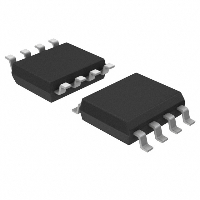
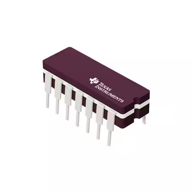
SN74LS02N Datasheet PDF & Pinout
- 邏輯類型: 或非門
- 電路數量: 4
- 輸入數量: 2
- 包裹: 14-PDIP

訂單滿 HK$250.00 即可享有免運

快速回應,快速報價

閃電出貨,售後無憂

原廠通路,正品保證
Electronics: Annoying problems getting started with logic circuits (SN74LS) (2 Solutions!!)
sn74ls02n
This IC gives you four separate two-input NOR gates, perfect for common logic functions. Since it’s part of the Low-Power Schottky (LS) logic family, you’ll find it runs efficiently, saving power but still quick enough for medium-to-high-speed applications. It uses a standard 5V power supply, which fits neatly into most digital setups.
With a propagation delay of about 10ns, it’s fast enough to handle typical logic processing tasks smoothly. Plus, the outputs deliver standard TTL signals, meaning you can directly feed multiple logic inputs without extra hassle.
It’s commonly available in a handy 14-pin DIP package, making it simple for you to install or swap out when needed. You’ll find it reliable within standard industrial temperatures (0°C to +70°C), so it’s ideal for automation control, signal processing, state detection circuits, and even computer peripheral interfaces. Overall, this chip makes your logic designs straightforward, efficient, and dependable.
sn74ls02n pinout

| 密碼 | 引腳名稱 | 描述 |
|---|---|---|
| 1 | 1年 | First Gate Output (Y) |
| 2 | 1A | First Gate Input A |
| 3 | 1B | First Gate Input B |
| 4 | 2年 | Second Gate Output (Y) |
| 5 | 2A | Second Gate Input A |
| 6 | 2B | Second Gate Input B |
| 7 | 接地 | Ground Pin (Power Negative) |
| 8 | 3A | Third Gate Input A |
| 9 | 3B | Third Gate Input B |
| 10 | 3年 | Third Gate Output (Y) |
| 11 | 4A | Fourth Gate Input A |
| 12 | 4B | Fourth Gate Input B |
| 13 | 4年 | Fourth Gate Output (Y) |
| 14 | 電壓控制電路 | 電源電壓(+5V) |
The SN74LS02N chip gives you four separate NOR gates, each with two inputs. Here’s a quick tip: the NOR gate only outputs a high (1) when both inputs are low (0). If either input or both go high, your output drops to zero.
When wiring this IC, make sure your power supply stays steady around +5V (±0.25V is fine), and always keep the ground pin properly connected to a solid ground. Don’t leave any inputs floating—tie unused inputs directly to ground or a stable voltage, or you might see unpredictable results in your circuit.
Another thing, don’t let the output pins drive more than 20mA of current each—going higher risks damaging the chip. And keep your input and output lines as short and direct as possible; that’ll keep noise and interference down, helping your circuit run smoothly.
sn74ls02n equivalent nor gate ic

| 範圍 | SN74LS02N | SN74HC02N | SN74ALS02N | CD4001BE |
|---|---|---|---|---|
| Logic Function | Quad 2-input NOR gate | Quad 2-input NOR gate | Quad 2-input NOR gate | Quad 2-input NOR gate |
| 電源電壓 | 5V (TTL Level) | 2V~6V (CMOS Level) | 5V (TTL Level) | 3~15V (CMOS Level) |
| 封裝類型 | DIP-14 | DIP-14 | DIP-14 | DIP-14 |
| 傳播延遲(典型值) | 10納秒 | 9 ns | 5 ns | 50 ns @10V |
| Output Current Capability | ±8mA | ±25mA | ±24mA | ±6.8mA |
| Power Consumption | Low (LS Schottky) | Very Low (CMOS) | Relatively Low (Advanced Schottky) | Very Low (CMOS) |
| 工作溫度 | 0℃~70℃ | -40℃~+85℃ | 0℃~70℃ | -55°C ~ +125°C |
If you’re thinking about swapping out the SN74LS02N, here’s what you should consider with alternative options. The SN74HC02N is a CMOS version—it’s great because it uses less power, works over a wider voltage range, and has stronger output drive capability. But keep in mind, the logic levels are slightly different from standard TTL, so double-check compatibility.
If your circuit demands speed, you might like the SN74ALS02N better. It’s faster, perfect for high-performance TTL circuits, but remember, it does use a bit more power.
For situations needing wider voltage flexibility (3V to 15V), or when speed isn’t your biggest concern, the CD4001BE could fit the bill. It’s slower and has a weaker output drive, but shines in low-speed or battery-powered applications.
Always confirm your replacement matches your voltage range, logic compatibility, output current, and speed requirements to keep your circuit running reliably.
sn74ls02n nor gate circuit example

Here’s how a typical TTL NOR gate circuit, like inside your SN74LS02N chip, works in simple terms. At the inputs (A and B), you’ll see Schottky diodes protecting your circuit from any high-voltage spikes, ensuring your signals stay clean. Both inputs feed into transistor bases through 4kΩ resistors, forming the basic switching logic.
If both your inputs are low (0,0), the transistors on the left stay off, activating the output stage transistor and giving you a high output (logic 1). But if either input (or both) goes high, the left-side transistors switch on, pulling the output transistor low, giving you a zero at the output.
For practical use, always power the chip from a stable +5V source and ensure a solid ground connection. Don’t let input voltages exceed TTL standards (0–5V) despite built-in diode protection. Keep the output current within safe limits (under 20mA), and route your PCB traces short and direct to avoid noise issues.
sn74ls02n truth table and applications
NOR Gate Logic:
| 輸入 A | 輸入 B | Output Y |
|---|---|---|
| 0 | 0 | 1 |
| 0 | 1 | 0 |
| 1 | 0 | 0 |
| 1 | 1 | 0 |
Here’s how you can practically use the SN74LS02N NOR gate in your projects. First off, it’s great for building basic logic circuits—think comparison logic or state-detection setups. You can also easily create simple oscillators to generate clock or square-wave signals.
If you’re working with flip-flops or latches, NOR gates help you set up SR latch circuits, providing basic memory functions. Additionally, these gates are handy for simple control and protection circuits, preventing unwanted input states or controlling relays and transistor switches.
They’re useful in cleaning up and shaping digital signals, too—perfect for signal inversion or buffering to interface with other digital parts.
Just remember a few practical tips: always keep your supply voltage steady around 5V (±0.25V). Don’t leave unused input pins floating; tie them to ground or a defined level. Limit each gate’s output current to under 20mA to avoid damage. Finally, when designing your PCB, keep signal traces short and direct to reduce interference and ensure reliable logic signals.
sn74ls02n wiring with arduino

| Arduino Pin | SN74LS02N Pin | 功能 |
|---|---|---|
| 5伏 | 14 (VCC) | Chip Power Supply (5V) |
| 接地 | 7 (GND) | Ground Connection |
| Digital Pin 2 | Pin 2 (1A) | Input Signal A |
| Digital Pin 3 | Pin 3 (1B) | Input Signal B |
| – | Pin 1 (1Y) | Output, Connected to LED Indicator |
Here’s an easy way to hook up your SN74LS02N NOR gate chip with an Arduino UNO for testing. Start by connecting the chip’s power pin (pin 14) to the Arduino’s 5V pin, and ground (pin 7) to the Arduino’s GND. Then, connect Arduino digital pins 2 and 3 to inputs 1A (pin 2) and 1B (pin 3) of the NOR gate. The gate’s output (pin 1) goes to an LED through a resistor (220–470Ω), with the LED’s other leg to ground.
When testing, the NOR gate output only goes high (LED lights up) when both Arduino pins are LOW. Use the provided Arduino code to cycle through all possible input combinations.
A quick tip: make sure the chip notch faces the right way to avoid mistakes. Keep wiring neat and short to avoid interference, and always ground unused inputs to maintain stable operation. Using a resistor with the LED prevents damage to your components, ensuring reliable results every time.
sn74ls02n nor gate oscillator circuit
Here’s a practical way to understand the SN74LS02N NOR gate oscillator circuit. You’re basically taking a NOR gate from the SN74LS02N chip and creating feedback using a resistor and a capacitor. When you feed the gate’s output back into its input, it causes the circuit to continuously switch states—generating a steady oscillation.
Think of the capacitor like a tiny battery that charges and discharges repeatedly. Each time it charges up and then discharges through the resistor, the input voltage flips, making the output flip as well. This keeps repeating, creating a continuous pulse or oscillation.
If you’re wondering how fast it oscillates, that’s mostly determined by the resistor and capacitor values. A simple rule to estimate frequency is: frequency (Hz) ≈ 1 / (2.2 × R × C). Keep in mind, stable power supply at around 5V and good decoupling on your chip’s power pin are key to reliable oscillation.
Use this simple setup for clocks, LED blinking circuits, or basic sound generators.




,SOT157-2.JPG)
,SOT523-1.JPG)

